0
\$\begingroup\$

I am fixing an old regulated load dummy that I use in my workspace. It was a mess and I want to modify its regulator side.

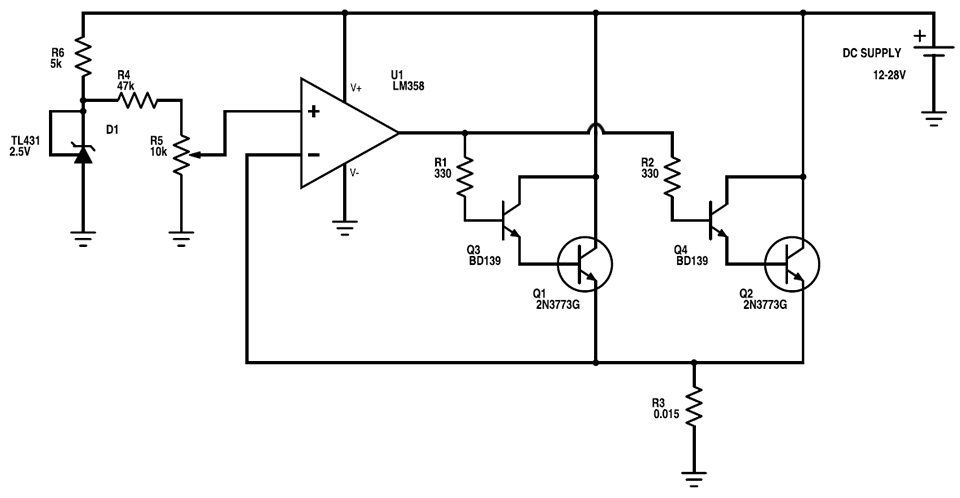
My question is: will the circuit showed in the image work properly? If you have any hints about possible upgrades, I would be grateful. I want to keep it simple as possible.

The regulation of load current is in range of 0-24 A.

enter image description here

I am aware, that this is not a modern design, but as I said I'm only fixing it and modified it a little bit. I need to keep these two NPNs there.

Also, there will be cooling fan control and temperature shutdown protection. Also fuse and protection diode. My question is only about the functional part.

Thank you.

\$\endgroup\$
1
  • \$\begingroup\$ Is your controlling opamp really powered from the supply-under-test? I can imagine bad failures in your dummy load if the tested supply fails or do funny things due to testing itself. A separate supply for the control circuitry will improve the reliability of the dummy. \$\endgroup\$ Commented Aug 25, 2015 at 5:34

2 Answers 2

5
\$\begingroup\$

Your circuit will not work.

1) 28 volts @ 24 amps is 672 watts. The 2N3773 is only rated for 150 watts, and this assumes a perfect heat sink capable of maintaining the transistor case at 25 C. Using a more reasonable thermal load of 100 watts, you'll need at least 7 transistors. You'll also need a bloody good heat sink with a fan.

2) Assuming ~8 transistors, this implies ~3 amps collector current per transistor max. If the transistor hfe is assumed (from the data sheet) to be about 20, you'll need about 150 mA per transistor base drive, or a total of about 1.2 amps total base current. An LM358 will never produce that kind of current, so you'll need a current booster for the base drive.

3) In order to get down to 0 amps load current, you'll need a negative supply voltage. First, you need it to allow the op amp to operate reliably near zero volts input from the sense resistor, and second you need some way to bleed off leakage currents through the pass transistors. Note that, if you select an op amp with rail-to-rail inputs, you can still get in trouble with parasitic IR drops in your power circuitry, so unless you are rather more knowledgeable about pcb layout than I suspect, a negative supply is still indicated.

4) Along this line, you should use a differential amplifier or instrumentation amplifier to sense your current - don't simply assume that the ground point of the sense resistor is at the same voltage as the ground point of your reference voltage. With 24 amps running around your circuit they almost certainly are not. And make sure you use a Kelvin connection on your sense resistor.

5) For stability, you'll need to provide small emitter resistors on each NPN. 0.1 ohm to 1 ohm will work well.

\$\endgroup\$
3
  • \$\begingroup\$ Thank you for answer. I mentioned 24A only for some kind of teoretical maximum. The DC supplies I'm testing can't even handle this current value. I have very good heatsinks with efficient cooling fan. No real 0 amp value is also not a problem. Can you tell me something more about these small emitter resistors you mentioned? What will happen if I leave it as it is in the image? \$\endgroup\$
    – przeski
    Commented Aug 24, 2015 at 22:13
  • \$\begingroup\$ @przeski - So, exactly how much current do you really want to handle? And what is the effective thermal resistance of the heat sink you do have - that is, what, exactly, do you mean by "very good"? \$\endgroup\$ Commented Aug 24, 2015 at 22:37
  • \$\begingroup\$ The emitter resistors prevent possible current hogging and thermal runaway. They are not necessarily needed, but they are good insurance. Transistors come with wide variations in gain, at least 3 to 1. If you have 1 high-gain transistor and 2 low-gain transistors, the high-gain unit will draw so much current that it can overheat. \$\endgroup\$ Commented Aug 24, 2015 at 22:45
1
\$\begingroup\$

General Schematic Review:

  1. I am calculating a maximum current of [2.5*10k/(10k+47k)]/0.015 = 29A. That's a touch more than the 24 you stated.
  2. In the worst case, your output devices have to dissipate over 400W each. That's pretty extreme.
  3. You may want to add a compensation network to the op amp.
  4. Your shunt resistor will dissipate up to 12W. Size accordingly.

Other Suggestions:

  1. You might want to add a testpoint/BNC/Banana/Something to the feedback from the shunt so that the user can see what they are doing when adjusting the current level.
  2. A cooling fan is not enough, a heatsink is required. Consider water cooling if available.
  3. Consider just buying several power resistors for your testing. You are setting out on a non-trivial design.
\$\endgroup\$
4
  • 1
    \$\begingroup\$ @WhatRoughBeast I started typing before I saw your post. Sorry for any redundancies. \$\endgroup\$ Commented Aug 24, 2015 at 21:44
  • \$\begingroup\$ Thank you for answer. I am aware of the power dissipation, and my heatsinks are quite big. It already worked with 15A current. I probably won't need bigger. 24A is just teoretical. :) Can you tell me more about this compensation network? Why it is in your opinion desirable in this design? \$\endgroup\$
    – przeski
    Commented Aug 24, 2015 at 22:01
  • 1
    \$\begingroup\$ For the long answer see this. The really short version: Feedback circuits sometimes oscillate and these oscillations can be fixed with a capacitor from the op amp's output to the op amp's inverting input and a resistor in the feedback. You may not have a stability issue but I always put pads for compensators on my boards just in case. \$\endgroup\$ Commented Aug 24, 2015 at 22:13
  • \$\begingroup\$ Also, you should increase R4 such that with the knob all the way up it doesn't break the output stages. \$\endgroup\$ Commented Aug 24, 2015 at 22:53

Your Answer

By clicking “Post Your Answer”, you agree to our terms of service and acknowledge you have read our privacy policy.

Not the answer you're looking for? Browse other questions tagged or ask your own question.