Welcome all. I have system with 5.1V PSU sourcing 20mA. My load is circuitry running of 5V sinking 15mA to 18mA. However, in extreme condition my load sinks 22mA. I need to test each PSU to see what is the output voltage while sourcing 22mA. I do not want to use resistor as it would require adjusting it for each PSU. I am interested exactly in 22mA value to see what is the voltage value of my PSU. What would be the best approach to loading my PSUs with precisely same current each time?
2 Answers
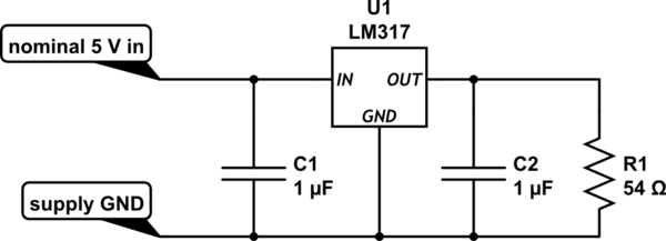
The simplest constant current sink is provided by an LM317, like this

simulate this circuit – Schematic created using CircuitLab
How does it work? The output is regulated to about 1.2 V, regardless of variations in the input voltage, so the 54 ohms will draw about 22 mA. Trim its value if you need the current set precisely. U1 also passes a fraction of 1 mA to ground through the ground pin. At this low current, you may get away without C1 or C2 for stability, but plan to use them just in case.
-
\$\begingroup\$ Thank you. Simple elegant solution! Used voltage regulators many times however as a voltage source. Funny how we look at particular component in one way failing to remember principles of it. Also follow up question. Many circuits are based on op-amp controlling BJT or FET e.g. forum.arduino.cc/index.php?topic=90343.0 Is there any benefit of this approach compare to resistor and voltage regulator you posted? \$\endgroup\$ Commented Apr 14, 2020 at 15:15
-
\$\begingroup\$ With this particular regulator, 4 V is the minimum you can sink from, due to its dropout, 40 V the maximum, though you could use an LDO instead, and an input cascode. The current isn't easily programmable. There's a minimum current of the regulator's I<sub>Q</sub>. Using an opamp, and pass element of a BJT or FET would allow you to circumvent all of these shortcomings, at the expense of complexity. Often it will come down to what parts you have in your stock box, and almost everybody has an odd 317 lying around. \$\endgroup\$– Neil_UKCommented Apr 14, 2020 at 15:26
-
\$\begingroup\$ Thank you. Very clear and satisfying answer! I will get to building the circuit. Thanks! \$\endgroup\$ Commented Apr 14, 2020 at 15:29
Programmable electronic load would be a professional tool for testing the voltage with given load current.
-
\$\begingroup\$ Thank you for your answer. I might look into it at later stage due to cost. \$\endgroup\$ Commented Apr 14, 2020 at 15:07
