0
\$\begingroup\$

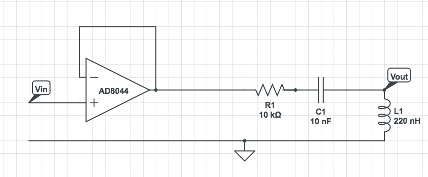
I have a signal for which I want to cutoff signal till around 3 MHz. Here is my circuit diagram.

enter image description here

The calculated cut-off frequency is 3.4 MHz. But when I use it, is just does not work, it seems to pass all frequencies. I am not using any load, I am just using the probe to measure the voltage across the inductor. Vin is the output from a Colpits oscillator.

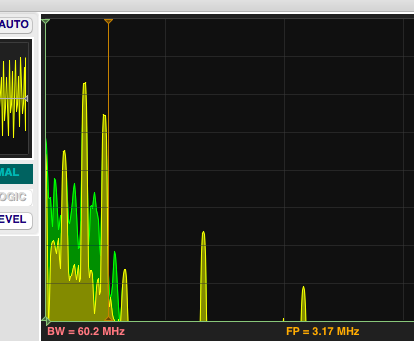
Here is a frequency domain snapshot from my oscilloscope. Yellow is the input and green is the output. The reddish vertical line is where frequency is 3.17 MHz, and green vertical line is 0MHz.

enter image description here

I have tried lot of stuff to work it out. But nothing seems to work. In low pass mode things work fine, but in high pass mode nothing seems to work. Your guidance will be greatly appreciated.

Capacitor datasheet (Class II): http://www.mouser.com/ds/2/212/F3101_Aximax-461059.pdf

Inductor: http://www.digikey.com/product-detail/en/api-delevan-inc/1025-04J/1025-04J-ND/4183026

\$\endgroup\$
6
  • 1
    \$\begingroup\$ What source and what load are you using it with? \$\endgroup\$
    – The Photon
    Commented Mar 11, 2017 at 3:06
  • \$\begingroup\$ Also, what actual capacitor and inductor did you use (links to datasheets are the best way to tell us). \$\endgroup\$
    – The Photon
    Commented Mar 11, 2017 at 3:13
  • \$\begingroup\$ Also, when calculating the cut-off frequency as 3.4 MHz, you negelected the effect of the resistor. The resistor isn't just damping resonance, it's adding a 2nd pole (looking like an RL and RC filter, not CL), and simulations says the circuit as drawn has high-pass cut-off at around 7 GHz, not 3 MHz. But nothing you build on a breadboard is going to give you that behavior. \$\endgroup\$
    – The Photon
    Commented Mar 11, 2017 at 3:24
  • \$\begingroup\$ I have added the details. Yes I am building it on breadboard. @ThePhoton \$\endgroup\$
    – sad-heart
    Commented Mar 11, 2017 at 3:30
  • \$\begingroup\$ Sorry, result of quick drawing, it is 10nF. Also Vin is the output from a Colpits oscillator. @ThePhoton \$\endgroup\$
    – sad-heart
    Commented Mar 11, 2017 at 3:33

1 Answer 1

1
\$\begingroup\$

First, go do a simulation of this circuit...R1 at 10 kohms messes everything up. Try 10 ohms instead. But still it should not be passing low frequencies.

Now go look at figure 11 in your capacitor datasheet. Your 10 nF capacitor turns into an inductor at around 3 MHz.

But this circuit should still be blocking low frequencies.

Most likely, your inductor is disconnected for some reason. Either a lead is broken or you have a bad solder joint or you tried building it on a breadboard and didn't get a good contact to the breadboard. So you're seeing just the effect of the RC in series between input and output, but then when the capacitor goes inductive you start to see a low-pass effect because of whatever the load is (10 pF oscilloscope probe, maybe).

\$\endgroup\$
2
  • \$\begingroup\$ Actually the 10nF turns into inductor at around 30 MHz. \$\endgroup\$
    – sad-heart
    Commented Mar 11, 2017 at 3:58
  • \$\begingroup\$ Ah, I misread the datasheet. But remember that's with the absolute minimum lead inductance. With a few cm of lead left on and whatever the breadboard adds, the performance in your circuit will be much worse. \$\endgroup\$
    – The Photon
    Commented Mar 11, 2017 at 4:02

Your Answer

By clicking “Post Your Answer”, you agree to our terms of service and acknowledge you have read our privacy policy.

Not the answer you're looking for? Browse other questions tagged or ask your own question.