1
\$\begingroup\$

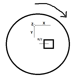
I want to measure the linear speed of a vehicle putting the accelerometer on its wheel. Assume the vehicle is moving at a velocity 70 KMPH and its wheel has a radius (R = Radius) 30 CM. I made this analogy, If the accelerometer will be placed on the wheel at position R/2 whose Z axis is now orthogonal to the wheel and let us assume there is no tilt in X and Y axis.

Image Axis of Sensor

The Accelerometer reading in X and Y should give the net accelerometer which is a_translational + a_rotational + TIGA = (R/2)alpha + (R/2) omega ^2 + TIGA where aplha is the angular accelartion and omega is the angular velocity and TIGA is the Tilt induced gravitational accelarion.

If my above observation is correct, how can i calculate TIGA factor? Will it change with the rotation degrees? How to balance it?

For calculating the speed (to correlate with 70 KMPH) i should integrate the accelration value in that period. In this case? Which accelration value from the accelrometer data should be considered? Should the a_rotational and TIGA factor must be removed from the data before integration?

\$\endgroup\$
2

4 Answers 4

0
\$\begingroup\$

This is what you are going to read from your accelerometer: $$ \begin{align*} a_{r}= & \frac{R}{2}\left ( 2\cos\vartheta \: \ddot{\vartheta } - \dot{\vartheta}^{2}\right )& +g \sin \vartheta\\ a_{t}= & \frac{R}{2}\left ( \ddot{\vartheta } - 2\sin\vartheta \: \ddot{\vartheta } \right ) & +g \cos\vartheta \end{align*} $$ and you want to get $$ v=R\dot{\vartheta} $$ If your speed is high enough (\$v=R\dot{\vartheta }\gg \sqrt{2gR} \approx 8.7km/h\$) you can neglect the other two factors and assume \$v=\sqrt{2a_{r}/R}\$ (this is the case for a normal travel by car).

Anyway the radial component can be easily filtered to obtain just \$\dot{\vartheta }\$, as the frequency of \$\vartheta\$ is way higher than the frequency of \$v\$.

I suggest you to simulate these equations and try to find a good strategy for your needs before going further. The following is a matlab code to simulate an experimental speed profile.

v = [20*ones(1,50*1e4) 20*2.^(-(1:(50*1e4))/(50*1e4)) 10+20/(50*1e4)*(1:(50*1e4)) 30*ones(1,50*1e4)];
plot(v)
disp('Velocity 72kph exponentially decreasing to 36kph then linearly increasing to 144kph')
pause

x = cumsum(v)/1e4;
theta = x / R;
xs = x + R/2*cos(theta);
ys = R/2*sin(theta);
xsd = diff(xs)*10000;
xsdd = diff(xsd)*10000;
ysd = diff(ys)*10000;
ysdd = diff(ysd)*10000+9.81;
ar = xsdd .* cos(theta(2:end-1)) + ysdd .* sin(theta(2:end-1));

plot(ar)
disp('Radial acceleration')
pause

plot(R*sqrt(-ar/R*2))
disp('Velocity recovered from radial acceleration')
pause
\$\endgroup\$
16
  • \$\begingroup\$ Thank you. Can you let me know, How did you get to calculate the first part of At in the expression(why are you substracting omega ??). Any reference !! As the accelerometer now is at rest and its position is at at + Y axis, so there is only one component of accelration which is gravity. hence, i should get A radial = g and a tangential = 0. using the above equation, it is different. \$\endgroup\$
    – Student15
    Commented Nov 6, 2015 at 9:38
  • \$\begingroup\$ I would also like to know, how did you assume Theta, with respect to which axis? \$\endgroup\$
    – Student15
    Commented Nov 6, 2015 at 9:42
  • \$\begingroup\$ I used your convention of clockwise positive angles (thus inverting the sign of derivatives), going from the x to the y axis in your picture. \$\endgroup\$ Commented Nov 6, 2015 at 9:45
  • \$\begingroup\$ Now, if you assume the Accelerometer at Y axis on my picture and it is at rest, the only acceleration it should get is gravity, at theta = 90, which is in the radial direction and there should be no tangential component(due to no rotation). Why we are not getting g as Ar and 0 as At? \$\endgroup\$
    – Student15
    Commented Nov 6, 2015 at 9:58
  • \$\begingroup\$ Regarding filtering i plan to go ahead as mentioned in this reference. SeeLink \$\endgroup\$
    – Student15
    Commented Nov 6, 2015 at 9:59
1
\$\begingroup\$

This is actually not a straightforward problem. The chain rule will bite you where you don't expect it to. Believe it or not, I'd low pass filter for the centripetal acceleration, use that and the tire circumference to calculate angular rate of the tire, and use that for speed.

\$\endgroup\$
1
  • \$\begingroup\$ Can you csuggest me about the LPF function? WHich cut off frewuqncy, which sample frequency and which order need to be used for LPF? What should i get after LPF of radial acceleration? If it will be omega, should i just multiply radius to get the speed (as v = radius * omega) \$\endgroup\$
    – Student15
    Commented Nov 17, 2015 at 11:00
1
\$\begingroup\$

You get a nice component of the acceleration due to the rotation. I would just measure that frequency and the velocity follows directly from the wheel circumference. This has the massive advantage that no calibration of the sensor position and orientation is needed.

To do this, calculate the mean value, subtract it from the signal, and find the zero crossings of the result. The time between successive positive crossings is a good measure of the time for one revolution. You may need to apply a small amount of low pass filtering to ensure you get just one crossing per revolution.

Or do an FFT of the signal and the largest frequency component is what you want (smoothing then comes for free).

\$\endgroup\$
4
  • \$\begingroup\$ Thank you. In the radial accelration part, if i take the FFT, I will have theta, theta' (omega), theta''(alpha) components. As theta, will have maximum frequency, then omega and then alpha. Do you mean that using a Band Pass Filter we should extract the theta' (Omega). \$\endgroup\$
    – Student15
    Commented Nov 9, 2015 at 12:12
  • \$\begingroup\$ Yes I think the most significant and high frequency component will give you $\theta$. This should be very obvious when you look at the FFT . \$\endgroup\$
    – Floris
    Commented Nov 9, 2015 at 12:23
  • \$\begingroup\$ I am not familiar with FFT, but it should give me the representation of signal in frequency domain. SO here i would get all the frequency as per the equation. As theta will have higher frequency , passing through LPF, we will get only the component of velocity (that means omega). Now this component multiplied with the radius , would give us the linear velocity. Is this approach correct? \$\endgroup\$
    – Student15
    Commented Nov 11, 2015 at 10:07
  • \$\begingroup\$ @Student15 yes that is exactly right. And since your FFT returns an array of (complex) amplitudes sorted by frequency, you could simply take the magnitude and look for the fist big peak starting from the high end. Once you have looked at a couple of spectra it should be obvious to see what processing you would need. \$\endgroup\$
    – Floris
    Commented Nov 11, 2015 at 11:14
0
\$\begingroup\$

Velocity is equal to the rotational velocity multiplied by radius, I suggest using this formula instead for your application, so you just have to do the math instead of using more electronics. So, use the formula: acceleration = (alpha)(radius) + (omega)^2(radius) and solve for omega.

\$\endgroup\$
1
  • \$\begingroup\$ Yes, but you did not consider the gravity component (TIGA) ! Which will have a significant effect. \$\endgroup\$
    – Student15
    Commented Nov 6, 2015 at 9:43

Your Answer

By clicking “Post Your Answer”, you agree to our terms of service and acknowledge you have read our privacy policy.

Not the answer you're looking for? Browse other questions tagged or ask your own question.