How do micro-controllers running at slow clock frequency (under 100 MHz) produce high frequency radio signal (2.4 GHz for example)? For example - ESP8266 runs on a clock speed of 80 MHz but is capable of wifi communication which requires a 2.4 GHz signal.
4 Answers
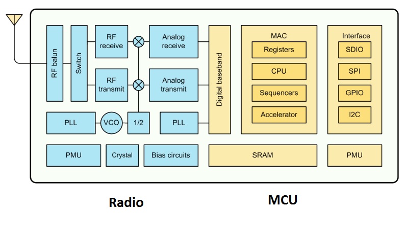
The 2.4 GHz carrier for the radio is generated with a dedicated voltage controlled oscillator. This oscillator will be locked to a low frequency reference with a PLL for stability. The data to be transmitted is not actually sent at 2.4 GHz - it gets generated by a digital to analog converter at several MSa/s. A mixer will be used to translate the output of the DAC up to the required RF channel frequency. There will also be dedicated signal processing logic that translates the actual packet data into baseband modulated samples that get sent to the DAC. The processor only provides the packet data to the beginning of the transmit chain, the rest of it is handled in dedicated digital and analog hardware. The receive chain will be similar to the transmit chain, except operating in the other direction and with a few additional components for tracking the carrier.
The ESP8266 is a SoC (system on chip) -- the microcontroller and WiFi modules are separate chips, however they share a common crystal -- typically 26 MHz. Separate PLL (Phase-locked loops) are used to generate the 80 MHz and 2.4 GHz frequencies for both the MCU and radio.
You can make a voltage controlled oscillator (VCO) to run at any frequency where there is readily available technology. You input a voltage and out comes a certain frequency. If you increase the voltage, the output frequency rises. You drop the control voltage and the frequency drops. In the case of this question we're talking about frequencies way-above normal clock speeds of MCUs.
If you then "sniff" and divide that output frequency down to a much lower frequency of (say) 10MHz using digital clock dividers then you can use simple logic gates to compare that divided down frequency with a rock-solid 10MHz xtal-based clock. There are various digital ways of doing this but the bottom line is, after processing that "comparison" signal, you can use a version of it to nudge (or align) the VCO with an exact and desired multiple of your reference 10MHz clock.
In this way, you get a very stable, very high frequency that the MCU (or FPGA or logic chip) doesn't really know anything about but has assisted along the way to produce. It's called a phase locked loop or PLL.
The microcontroller doesn't process signals or data at 2.4 GHz, just controls separate oscillators and modulators/demodulators that generate and extract data from them.
It's somewhat analogous to an MCU controlling a LED -- the light from the LED is at 4x10^14 Hz, but the MCU can turn it on and off.

