30
\$\begingroup\$

What would be the least expensive way to boost a DC voltage?

The aim is to convert 1.2 V/1.5 V (from an AA/AAA cell) to 3.3 V to power a small 8-bit microprocessor, like Atmel ATtiny45 or ATtiny2313, and also (if possible) 6 V to power a buzzer.

Also, what would be the maximum current one could draw safely from an alkaline battery, after boosting it to 3.3 V/6 V?

Finally, how I could compute the duration for which the alkaline battery would last, given a certain consumption?

\$\endgroup\$
11
  • 4
    \$\begingroup\$ You probably find some of the answers in a datasheet for the alkaline battery. For a primer on DC-DC converters you could have a look here: eevblog.com/2011/01/17/… \$\endgroup\$
    – 0x6d64
    Commented Nov 4, 2011 at 13:10
  • 1
    \$\begingroup\$ Looks like the attiny45 can go down into the 1.8-2V range and depending in your application, you may be able to suspend into a low power mode at times to save some draw on the battery. There's cheap, small PIC and TI MSP430 chips in the starter range that offer crazy small power draws. \$\endgroup\$
    – rfusca
    Commented Nov 4, 2011 at 16:40
  • 3
    \$\begingroup\$ Maybe I'm missing something obvious, but the simplest solution (and least expensive) is to just take two/four 1.5V batteries and put them in series to get your ~3.0V/6.0V to power your microcontrollers. \$\endgroup\$
    – dr jimbob
    Commented Nov 4, 2011 at 17:53
  • 1
    \$\begingroup\$ @jimbob thanks. Sometimes we do overlook the obvious :-), but in this case I had considered series combination. However, the challenge for my application is also size/weight, apart from cost. \$\endgroup\$
    – bdutta74
    Commented Nov 5, 2011 at 9:53
  • 1
    \$\begingroup\$ @Codism thanks. "Lease expensive" was part of my question statement on purpose :-). Li-ion's cost along with charging/battery-mgt, LDO etc., is about 5x the target cost of my entire project. \$\endgroup\$
    – bdutta74
    Commented Nov 5, 2011 at 9:55

7 Answers 7

42
\$\begingroup\$

There's a technique called a charge pump with which you can make a voltage doubler, but that will only give you 3V from a 1.5V cell, and even less from the 1.2V cell. I'm still mentioning it because several microcontrollers these days will work with voltages down to 2V. A charge pump can only supply limited current, enough to power the microcontroller, but extra power devices like motors or relays are out. The voltage will also drop under load. So not ideal. The LM2660 is a switched capacitor charge pump.

The better solution is a switching regulator. These exist in two major topologies: "buck" to go from higher to lower voltage, and "boost" to go from lower voltage to higher. So you want a boost regulator. Major manufacturers include Linear Technologies (more expensive) and National Semiconductor (recently acquired by Texas Instruments). The LM2623 can operate on input voltages as low as 0.8V.

About current and battery life. I'll assume you're working with 1.5V batteries. The ones here on my table are rated for 2300mAh, so let's use that value. Also let's say your microcontroller plus extras need 100mA at 3.3V. That's 330mW. If the switcher is 85% efficient that means it draws 330mW/0.85 = 390mW from the battery. That's at 1.5V, so you'll draw 260mA from the battery. The battery is rated at 2300mAh, then your device can run for 2300mAh/260mA = 9 hour on one charge.
If you plan to load the battery rather heavily, I would remain below 2300mA, which will drain it in 1 hour.

\$\endgroup\$
5
  • 2
    \$\begingroup\$ Another topology to consider for some applications is the flyback converter. Generally flyback converters are used to convert from one polarity to another, but if the power source is 'floating' (as would be the case with batteries) they have the advantage that one can use the same transistors regardless of whether the input voltage is higher or lower than the desired output. One disadvantage is that all of the energy has to be handled by the coil. By comparison, if converting from 2 volts to 3 volts, only 1/3 of the energy would have to be handled by the coil. \$\endgroup\$
    – supercat
    Commented Nov 4, 2011 at 16:55
  • \$\begingroup\$ Thanks @stevenvh, for a very comprehensive answer, with options. You've mentioned 2300mAh... are these the Duracell, Energizer kinds ? I am finding it hard to figure out the mAh rating of regular drugstore (non long-life kind) Alkaline batteries. \$\endgroup\$
    – bdutta74
    Commented Nov 5, 2011 at 10:11
  • \$\begingroup\$ @supercat, thanks for suggesting the option. Need to read up some more on the flyback converter option. \$\endgroup\$
    – bdutta74
    Commented Nov 5, 2011 at 10:12
  • \$\begingroup\$ @icarus74 - The 2300mAh is a Memorex NiMH AA rechargeable. I also have a pack of Duracell Plus Alkaline AAs (MN1500), but those don't have capacity info. \$\endgroup\$
    – stevenvh
    Commented Nov 5, 2011 at 10:54
  • \$\begingroup\$ hmm. Alkaline battery discharge curves / full data-sheets are something I've never managed to find for the drug-store AA cells. I did find this generic Magnesium Alkaline dry-cell whitepaper, which gives some good information. \$\endgroup\$
    – bdutta74
    Commented Nov 7, 2011 at 19:21
24
\$\begingroup\$

To make a higher power voltage from a battery like that takes a particular type of switching power supply called a "boost converter". This uses a inductor to make spurts of higher voltage. The concept is the same how a hammer makes spurts of much higher pressure than your arm can deliver to the nail directly.

There are chips out there that integrate much of this. Linear Technologies, ST Micro, TI, and various others make such chips. Some of the offerings from Microchip are quite nice within a narrow voltage range as you have.

Making higher voltage is OK, but these chips are still limited to the basic laws of physics. They can't provide more power out than in. Since power is voltage times current, the output current must go down as the voltage goes up. Just like with the hammer, your arm has to put in much more motion than is imparted to the nail in return for higher force out. Of course there will be some loss too. Anything over 90% is quite good. Let's say for purpose of example that your boost switcher is 80% efficient and it is making 3.3V at 100mA out from 1.3V in. 3.3V * 100mA = 330mW. Accounting for the loss in the switcher, 330mW / 80% = 413mW in. 413mW / 1.3V = 317mA, which is the current that will be drawn from the battery.

In this example, the battery current is 317mA, which is within range of what a AA type can sustain for a while. To get some idea how long the battery will last, you have to look at the battery capacity. This is expressed in current*time, like mA-hours. Let's say your AA battery has a capacity of 2 A-h. At first approximation, 2 A-h / 317 mA = 6.3 hours run time. However, there are a lot of things that mess up this basic analisys. For one thing, the current won't be 317mA over the whole discharge life of the battery. As the battery voltage gets lower, the switching power supply will draw more current. Temperature also greatly effects battery capacity. If this is meant to run outdoors in a cold environment, you might only get 1/2 or less of the rated battery capacity. The current itself effects capacity too. 300mA for a AA is probably not to the point where it degrades capacity significantly, but 1A certainly would be. You might get 2.0 A-h at 300mA, but only 1.6 A-h at 800mA. I'm making up numbers. These are probably not totally ridiculous for most AA batteries, but you really have to look at the battery datasheet yourself.

\$\endgroup\$
1
  • 1
    \$\begingroup\$ Thank you @Olin. Have upvoted, and I wish I could accept 2 answers. Your explanation is detailed and clear, and between Steven & your answers I learnt a lot. I just picked the answer order to be fair. \$\endgroup\$
    – bdutta74
    Commented Nov 5, 2011 at 10:06
11
\$\begingroup\$

Answers given will either not work in the real world versions of what you describe or are far from lowest cost.

Steven's LM2623 datasheet is a reasonable choice and will start on 1.1V and run on 0.9V but the IC costs about 60 cents.

If you genuinely want lowest cost then a properly engineered version of the Joule Thief is a good candidate. I use that name as it will lead you to many many variants but the original form is not very efficient. However, once you have the idea you can look at the options and choose one.

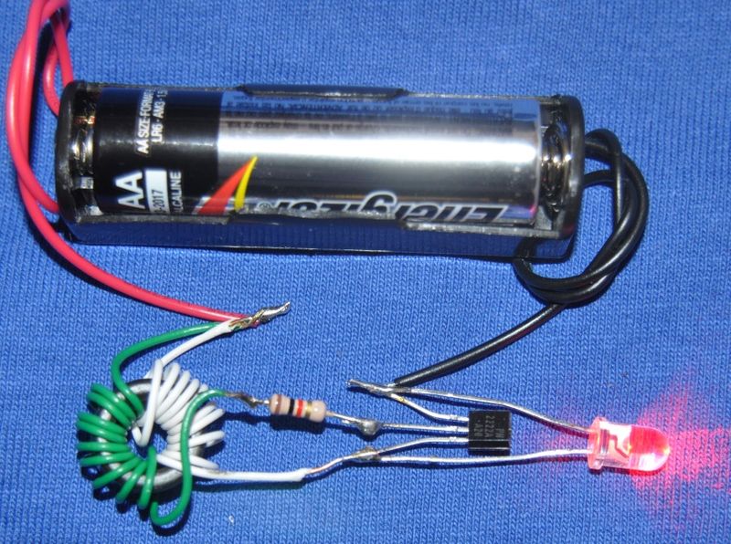
The "Joule Thief" is a one transistor self oscillating boost converter using an inductor main winding plus an inductor feedback winding. For DIY use you could build one for free from almost any modern scrapped electronic device or if buying new or surplus parts could build one with 10 to 20 cents of parts.

Here is a good example of a DIY Joule Thief page

The composite image below is made of 3 images from the above page:

enter image description here

Others - You can build boost converters with one transistor and two separate inductors - advantage is no need for two windings. And The classic Colpitts oscillator uses an untapped inductor.
A number here and


Other versions:

Good

A few zillion others


Wikipedia:

enter image description here


Added:

The basic Joule thief is not a marvellous design. It's outstanding feature is that it does work in many cases, thereby introducing energy conversions, SMPS, boost converters and more to many relatively inexperienced and uneducated electronics dabblers.

Various thoughts on regulated versions can be found by looking throiugh this collection (YMWV).

I stumbled upon a few prior stack exchange Joule Thief answers that seem to have some relevance. Searching for "Joule Thief" on this site will turn up a few more.

How can I calculate a Joule Thief

alternative fix to: How can I calculate a Joule Thief

Both December 2012


Various one cell to LED drivers here

\$\endgroup\$
4
  • \$\begingroup\$ Thanks Russell. I really like this true-blue DIY approach. Got a few questions though, will post each as a comment here, and hope taht you could answer. \$\endgroup\$
    – bdutta74
    Commented Jun 6, 2013 at 5:01
  • \$\begingroup\$ 1. In the tutorials I didn't find any explanation about the ratio of turns, number of turns for the inductor main + feedback windings. Do the no. of turns have to be same for main & feedback ? \$\endgroup\$
    – bdutta74
    Commented Jun 6, 2013 at 5:02
  • \$\begingroup\$ 2. Is there a way to determine the voltage that the input is boosted to, via the number of turns ? Or number of turns only determine the amount of current that could be drawn ? \$\endgroup\$
    – bdutta74
    Commented Jun 6, 2013 at 5:03
  • \$\begingroup\$ 3. Should I assume that the boosted output is unregulated, and the boost is a nearly constant factor, applied to the input voltage ? \$\endgroup\$
    – bdutta74
    Commented Jun 6, 2013 at 5:04
6
\$\begingroup\$

The cheapest ICs for boost converters I know are the 34063 and the MCP1640. The output of the MCP1640 only goes up to 5V, but it is more efficient and seems easier to use (fewer external parts) than the 34063, except that the MCP1640 is only available as SMD.

\$\endgroup\$
3
  • \$\begingroup\$ Thanks @starblue. Will definitely look at it, but as you mention SMD only, that'd be a problem for me. While I have done some SMD work, but only with great difficulty. Don't have the right setup (tools and patience) to do SMD work. \$\endgroup\$
    – bdutta74
    Commented Nov 5, 2011 at 10:03
  • \$\begingroup\$ The 34063 is available as a DIL package. \$\endgroup\$
    – starblue
    Commented Nov 5, 2011 at 11:46
  • 2
    \$\begingroup\$ MC34063 does not work at low enough voltages to meet his need. \$\endgroup\$
    – Russell McMahon
    Commented Jun 5, 2013 at 14:38
6
\$\begingroup\$

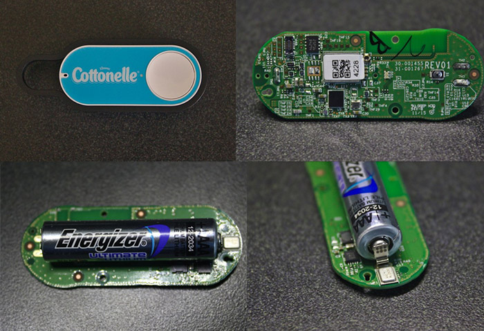
The Dash Button

amazon dash button

The [Amazon] Dash Button operates at 3.3 V boosted from the battery’s nominal 1.5 V, drawing 200–300 mA from the battery when on and 2.3 μA when in sleep. This means the ~1200 mAh battery should be able to power the device for at least four hours while on and decades while in sleep. Since the button is only on for a few seconds when activated, it can probably be used close to 1000 times before the battery dies. Thus, the button should become obsolete long before the battery is depleted.

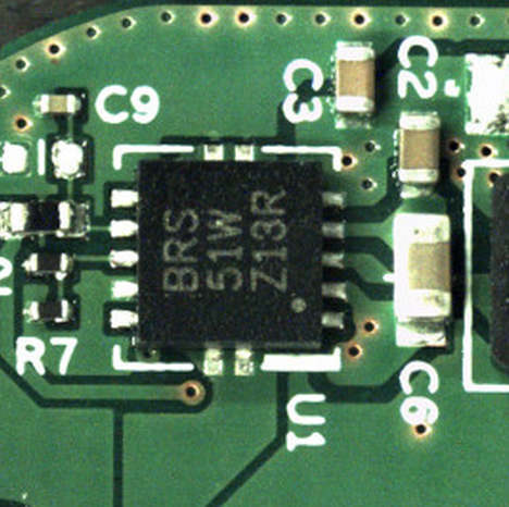
boost converter

[It was] pointed out that U1 is probably a TI TPS61201 boost converter; the footprint, package markings, and pinout seem to fit.

From Amazon Dash Button Teardown

\$\endgroup\$
1
  • \$\begingroup\$ These are more than a dollar each per Octopart and will likely not meet the "Least Expensive" need to satisfy the question. But you're on the right track -- if you find a cheaper chip. \$\endgroup\$ Commented Apr 30, 2022 at 16:40
3
\$\begingroup\$

There are plenty of cheap and cheerful (or nasty maybe?) circuits on eBay or AliExpress if you search for a "USB Boost Circuit" or similar. These sell as a finished device for $0.30 - $2 depending on how many you want, are usually around 25mmx19mm, and if you look carefully at the photos you can sometimes read the control IC product code and work out what it is (although better yet some AliExpress suppliers will provide the datasheet in the listing). Pretty much every one of these will have a resistor divider which scales the output voltage to a reference voltage and changing the resistor on one leg of divider will let you get 3V3 instead of the 5V they ship as.

I bought 50 to get the price down, desoldered the USB sockets, soldered on double AA holders (at $0.19), and now I have a stash of cheap power supplies that I can set to whatever voltage I need for a project. I don't think you can really beat $0.50 per power supply.

ETA: You shouldn't need the datasheet to find the voltage divider or calculate the new values for it, it should be obvious which is the divider (i.e. a pair of resistors from one IC pin, one resistor to ground one to output voltage) and the reference voltage they are targetting can be calculated from the existing divider and the 5V output currently set. On mine for example I have a \$15k\Omega\$ to ground and \$47k\Omega\$ to output so I have a reference voltage of \$\frac{15}{47+15}\times5V \approx 1.2V \$, and thus to get 3V3 output we can (by happy coincidence) swap either resistor for a \$27k\Omega\$ depending on whether you want to be marginally higher or lower than 3V3.

\$\endgroup\$
4
  • 1
    \$\begingroup\$ Why the downvote? OP wanted the least expensive solution which I think I've provided. \$\endgroup\$
    – Parakleta
    Commented Nov 22, 2016 at 0:54
  • \$\begingroup\$ As the OP, I liked the answer and upvoted. ESE is extremely strict about "product recommendation" policy. Things that talk of specific products, sources, price is frowned upon -- been burnt couple of times. However, in the overall context, I think you've edited the answer to add nature of information that is considered useful and generic (which is why the up-vote). The question was asked 5yrs back, and IIRC such ready-to-use 'blocks' were not readily available. \$\endgroup\$
    – bdutta74
    Commented Nov 22, 2016 at 7:36
  • \$\begingroup\$ I didn't know about "product recommendation" policy. I specifically didn't link to anything since I was just providing general suggestions though. I find 90% of electronics engineering these days is product/source/price of components to achieve a final product with the required functionality for the best price. I know the question is quite old, but unfortunately stack questions live for ever and need new answers as technology and solutions change. 5 years ago the little USB boost devices existed as "USB Emergency Charger" for $10 as finished products you would have to dismantle. \$\endgroup\$
    – Parakleta
    Commented Nov 23, 2016 at 0:47
  • \$\begingroup\$ not sure if you've been on ESE for very long, but the general drift is that this is not really a Arduino'sque lego-block construction (aka Maker) community, although you'd find plenty Q&A along those lines. Q&A that have embed fundamentals of electronics theory are better appreciated. As I wrote, I liked the answer for practicality of approach. Yes, much water has flown under the bridge in the last 5 years. \$\endgroup\$
    – bdutta74
    Commented Nov 23, 2016 at 9:54
1
\$\begingroup\$

Consider switching to a battery in the voltage you want, and possibly a second one for the buzzer.

(If you actually need 1.2V/1.5V for something else in the same circuit, than this does not apply)

\$\endgroup\$
2
  • \$\begingroup\$ thanks for answering. Multiple batteries make my project big+heavy+clunky. But I admit, I never mentioned size/weight as a requirement :) \$\endgroup\$
    – bdutta74
    Commented Nov 5, 2011 at 10:02
  • 1
    \$\begingroup\$ There are many buzzers that are specified at 3.3V and actually make noise way below that. \$\endgroup\$
    – Jon Watte
    Commented Jun 7, 2013 at 4:58

Your Answer

By clicking “Post Your Answer”, you agree to our terms of service and acknowledge you have read our privacy policy.

Not the answer you're looking for? Browse other questions tagged or ask your own question.