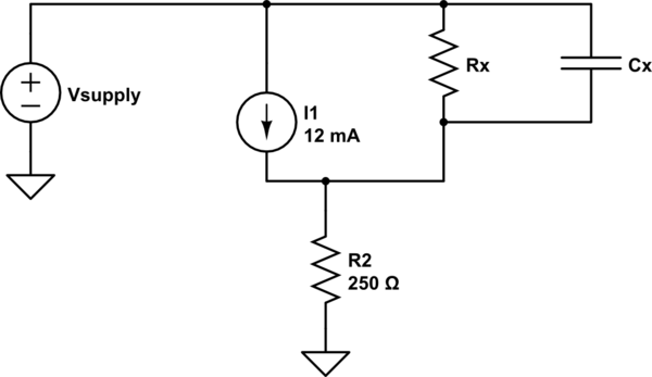
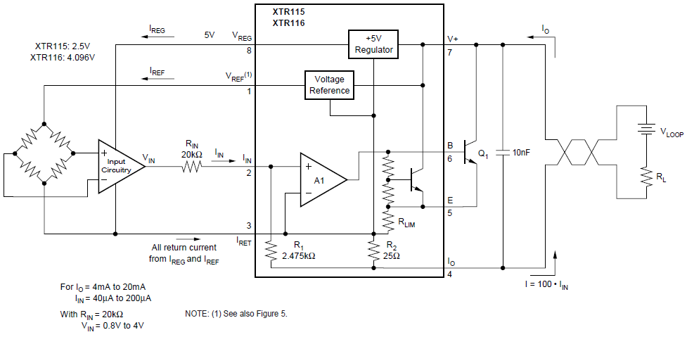
The output impedance Rx || Cx will look something like this:

simulate this circuit – Schematic created using CircuitLab
Where R2 is your receiver resistance (in this case to give you 1-5V).
Vsupply must be high enough that the voltage across I1 is in the range of +7.5 +36 for the transmitter to function properly. At 12mA (mid-scale) the voltage across R2 is 3.00V and should remain at about that level for Vsupply in the proper range.
You can measure the DC output impedance by varying Vsupply from (say) 10V to 30V and measuring the change in voltage \$\Delta V\$ across R2 so
Rx = \$R_2(\frac {20}{\Delta V} -1) \approx R_2(\frac {20}{\Delta V}) \$
For example, if the voltage across R2 varies by 100uV for a 20V change in Vsupply, the output impedance would be 5M\$\Omega\$
For AC analysis, Cx will enter into the complex impedance and there may be other effects as well, but leave that for another time.


