0
\$\begingroup\$

Andy aka, rioraxe and Daniel thank you very much for taking the time to respond to my first question.

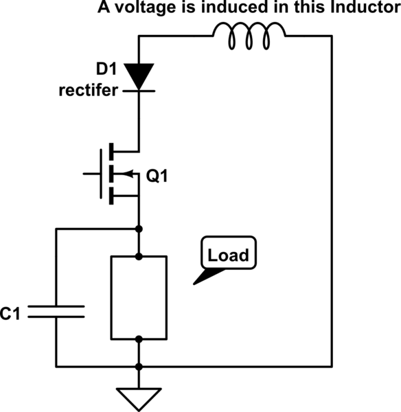
In the schematic below, an A/C voltage is induced in the inductor. The MOSFET is used to control the voltage to the load.

1) What would be the best way to handle the resulting freewheel current when the MOSFET is switched off? And as was said in answer to my first question, I would like to be able to reuse the energy that is stored in the inductor.

2) How could I get the flyback current to die down very quickly? This would be way more important to me than being able to reuse the stored energy.

<

schematic

simulate this circuit – Schematic created using CircuitLab

\$\endgroup\$
2
  • \$\begingroup\$ There is no power source, there is no freewheel current. \$\endgroup\$
    – Daniel
    Commented Apr 13, 2016 at 4:24
  • \$\begingroup\$ How is the 'A/C' voltage induced into the inductor? \$\endgroup\$ Commented Apr 13, 2016 at 6:45

1 Answer 1

1
\$\begingroup\$

Is that top inductor just one winding of a transformer?

In any case: when the mosfet switches off, the current in the inductor is going to (nearly) instantly drop to 0. Since the right side of the inductor is grounded and you have a very large sudden decrease in the right to left current, what you will find happening is the voltage on the left side of the inductor will fly upwards. C1 may ensure that your mosfets source voltage remains the same, so you will be looking at a large voltage appearing across the series combination of your diode and the effective S to D diode inherent to your fet, which appears in the opposite polarity or your existing actual diode. Whether or not this is a problem likely depends on your particular diode and fet, but if it is you could use a unipolar transient voltage suppresion diode (will look effectively like a zener with cathode on inductor diode junction and anode on ground.) to clamp the positive flying voltage to a reasonable level.

How quickly the flyback voltage dissipates depends on the effective resistance (instantaneous V/I) of your tvs diode.

Also note: the energy stored in an inductor is proportional to the (square of the) instantaneous current through it. Thus, once you open the get switch and the current in the inductor drops to 0, the energy stored in your inductor drops accordingly.
\$\endgroup\$
4
  • \$\begingroup\$ ChateauDu, I truly appreciate your input. Question: 1) When Q1 is on, current flow through the inductor from right to left (i.e, from right side of the inductor down through D1, Q1, the load and then to ground). What is the direction of the current (flyback) through the inductor when Q1 is turned off? 2) A TVS diode is normally connected in reverse in a circuit (i.e, with the cathode to the +ve voltage), but how would the TVS behave if it was connected the other way around; suppose D1, in our circuit here, was replaced with a TVS or regular zener, how would either of them behave? \$\endgroup\$
    – Dave
    Commented Apr 13, 2016 at 15:45
  • \$\begingroup\$ No problem. 1) When Q1 gets turned off, the inductor is trying to maintain whatever current was flowing through it at the moment before Q1 switches off. Because the inductor is now trying to force this current across a very high impedance load, the voltage on its left side now skyrockeys upwards. \$\endgroup\$
    – ChateauDu
    Commented Apr 14, 2016 at 3:27
  • \$\begingroup\$ 2) if your d is replaced with a zener, it could turn on in reverse mode when your inductor is stimulated in the opposite direction as you are nominally using, i.e. if it's left side voltage shoots negative. In this case, the inherent source drain diode in your fet has its anode at ground and the cathode at the cathode of the zener, thus you could have current flow upwards through the series combo of the fet inherent diode and the zener \$\endgroup\$
    – ChateauDu
    Commented Apr 14, 2016 at 3:33
  • \$\begingroup\$ ChateauDu, Thanks so much. I now understand what is going on in the circuit. \$\endgroup\$
    – Dave
    Commented Apr 16, 2016 at 17:44

Your Answer

By clicking “Post Your Answer”, you agree to our terms of service and acknowledge you have read our privacy policy.

Not the answer you're looking for? Browse other questions tagged or ask your own question.