0
\$\begingroup\$

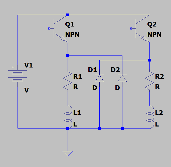
So, here is the context. We have two electromagnets (modeled as R1 and L1, and R2 and L2), their state is dictated by a microcontroller which sends PWM to Q1 and Q2. The signal sent to Q1 and Q2 is a square wave around 80 Hz. The two square waves have the same period and amplitude, but an 180 deg. phase shift, so when Q1 is open, Q2 is closed.

Here is the idea: when the switch to an inductor is suddenly opened, a flyback potential is created across the inductor. A diode pointing to the other side of the inductor is usually added to avoid arcing.

My idea is that I apply this flyback potential to the other inductor, some of the energy stored in inductor 1 as moving current will be transferred to inductor 2 through the diode. I have an intuition that since the current through inductor 2 can't change instantly, this setup would still give me sparks though.

The question is, would this increase the efficiency of the system compared to connecting each diode to the corresponding inductor? Or am I misunderstanding flyback voltage to begin with? If so, what would be the corrected way to "recycle" the energy stored in the first inductor?du
\$\endgroup\$
5
  • 3
    \$\begingroup\$ If you drag D2 to the left of D1 you will see that you just have regular snubber diodes across each inductor. There is no cross-feed of current from one to the other. Your little plan isn't going to work. \$\endgroup\$
    – Transistor
    Commented Jul 4, 2019 at 21:06
  • \$\begingroup\$ Do you want each electromagnet to turn on and off at 80Hz, or is the PWM used to adjust the strength of one relative to the other? \$\endgroup\$ Commented Jul 4, 2019 at 21:37
  • \$\begingroup\$ @Transistor So, if Q1 opened and Q2 closed, the current through L1 will simply come down as it would if the L2 branch wasn't there at all... Yes this makes sense. So all the magnetic energy stored in L1 will be lost, as heat in R1? And this is inevitable? \$\endgroup\$
    – Xylord
    Commented Jul 5, 2019 at 0:01
  • \$\begingroup\$ @BruceAbbott I want the electromagnets to follow this cycle: EM1 ON - EM2 OFF - 0.00625 s EN1 OFF - EM2 ON - 0.00625 s The voltage across the electromagnets may vary, but overall this should still be close to a square wave. So I'd use the PWM to both control the strength of the electromagnets, and to switch them on and off at 80Hz. I was thinking of using MOSFETs. \$\endgroup\$
    – Xylord
    Commented Jul 5, 2019 at 0:06
  • 1
    \$\begingroup\$ What is the schematic intended to show? \$\endgroup\$
    – Andy aka
    Commented Jul 5, 2019 at 7:23

1 Answer 1

2
\$\begingroup\$

An idea...

If the diode anodes weren’t tied to GND, what happens? You get a large, negative voltage through each diode when each transistor turns off and the coil flux collapses. Add a capacitor to capture the charge and you just made an inverting boost converter.

Rearrange things a bit: put the npn’s on the low side and connect the coils to the supply, flip the diodes to make it a positive boost. This could be fed back to the supply through another diode maybe, or used for another purpose.

\$\endgroup\$

Your Answer

By clicking “Post Your Answer”, you agree to our terms of service and acknowledge you have read our privacy policy.

Not the answer you're looking for? Browse other questions tagged or ask your own question.