How can we use potentiometer to regulate voltage form o-5v?
That is, if we rotate the potentiometer it will give some voltage variation as output. If there any circuit available please let me know the function of that circuit.
How can we use potentiometer to regulate voltage form o-5v?
That is, if we rotate the potentiometer it will give some voltage variation as output. If there any circuit available please let me know the function of that circuit.
Now that you have provided more information, a voltage regulator is not actually what you want. I will go ahead and leave that part of the answer in here for reference though.
What you actually want is a voltage divider. A voltage divider looks like so:
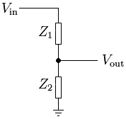
and follows the formula of  .
.
Selecting Values for your System
Note, Majenko already answered with a simpler method, but since you still had questions I will give you a slightly different approach to it in the hope to grow your understanding more.
The specifics of the values you choose will be related to your specific circumstance, but let me give you an example:
First lets set Vin to be a constant 10v. In order to get down to 0v you will have to set Z2 to be your pot, that way when you pot is at 0 ohms, Vout is 0v.
Now you need to select the values for Z1 and select the max value of your pot. The best way to approach this is to look at your current draw from Vin in your worst case, which is when Z2 is at 0. You probably want to keep your current in the lower mA range, so I will randomly select 5mA, to solve for Z1 you use ohms law. V/I=Z1 or 10v/5mA=2Kohm
Now that you know Vin, Z1, and your desired range of Vout, you need to solve for Z2. The max Vout that you want is 5v, so lets plug that all into the voltage divider equation.
5v = (Z2/(2kohm+Z2))*10v => Z2 = 2Kohm meaning that your pots max resistance should be 2 Kohm
Correlating Voltage to degrees on the Pot
Now that you have a system setup that outputs 0-5v, I will skip past the sampling of the voltage and move on to how to relate your measured voltage to the position of the pot.
This will depend directly with the range of motion of your specific pot, but for example purposes I will assume a range of 180* and that you are using a linear pot.
If you look at the equation for the voltage divider, you will find that the output voltage is not so linear. In fact if you were to plot it, it would look like so:
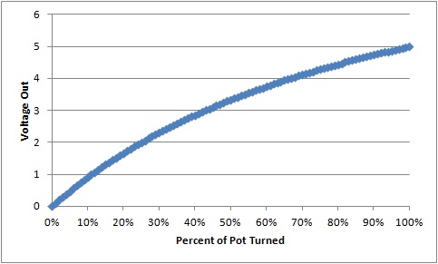
If you use Majenko's method, you will get a linear relationship
You can still determine what the resistance your pot is at, it will just require a little bit of math. I will let you go ahead and do this math yourself and assume you can find the resistance of your pot. Once you get this resistance, you can just divide it by the max resistance of your pot (2 kohm) in this example. This will give you a percentage that you can then multiply your pots range of motion by and get the pots current location. So if you come up with 1kohm, divide that by 2kohm, and get 50% then multiple 50% by 180* and your pot is at 90*.
First you must understand what it means to regulate a voltage. The basics principal of a regulator is to take a variable higher voltage and produce a constant lower voltage. You can use a voltage divider with one of the resistors being a potentiometer to create a lower voltage, the problem is that your voltage out will depend on both the voltage in as well as the load of the output (ie, what your voltage regulator is powering).
So you must use a regulator to get a constant voltage out. In order to achieve the ability to adjust the output voltage with a pot, you will want to use something like the LM117. Their website shows an example circuit as shown here, where R2 is your pot:
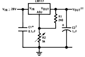
Or more precisely the datasheet says:
In operation, the LM117 develops a nominal 1.25V reference voltage, VREF , between the output and adjustment terminal. The reference voltage is impressed across program resistor R1 and, since the voltage is constant, a constant current I 1 then flows through the output set resistor R2, giving an output voltage of
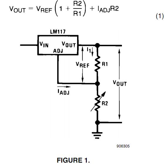
Since the 100μA current from the adjustment terminal represents an error term, the LM117 was designed to minimize I ADJ and make it very constant with line and load changes. To do this, all quiescent operating current is returned to the output establishing a minimum load current requirement. If there is insufficient load on the output, the output will rise
This will allow you to regulate all of the way down to 1.2v, but is not able to go beyond that, and you will be hard pressed to find a regulator that can do anything much better.
The arrangement is what is known as a "Voltage Divider".
Usually this is made up of two resistors in series between the 5V and the Ground connections. The center tap where they join is the new output voltage, which is at the ratio of the two resistors:
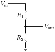
\$V_{out} = V_{in} \times \frac{R_2}{R_1+R_2}\$
You can replace the two resistors with a potentiometer in the exact same arrangement. The wiper of the potentiometer is the center tap of the voltage divider, and the two resistances between the wiper and either end are the two resistors R1 and R2.