1
\$\begingroup\$

schematic

simulate this circuit – Schematic created using CircuitLab

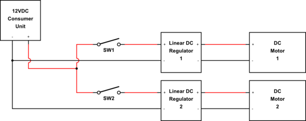
I am building a twin air pump for a pond, powered by a 50W PV system with charge controller connected to a DIY fused DC consumer unit. I have a project box with two switches - each switch goes to a pre-made (fan controller) LM317 linear adjustable voltage regulator, each going to a simple DC motor. The idea is to have each pump independently switched and adjustable but running off one 12V output from the consumer unit - because it will be attached to a single timer.

When tested on separate outputs on the consumer unit, they worked fine, but when I forked them at the point of entry into the project box (before the switches of course) they worked erratically for a few seconds during adjustment. After a while the potentiometers 'died open' allowing full speed only. There was no visible sign of damage to each circuit board however.

I've now obtained another pair of these regulator circuits - but before risking them again is there a best practice method of protection here? My initial thoughts were a diode on each (+) between where the line forks and the switch and/or diodes on the line between each regulator and motor. I have 1N4001 silicon diodes and SB560 Schottky diodes available. Are diodes enough or is there something else needed here?

Parts used:

2x Mini toggle SPST switches. Rated 5A @ 125VAC / 2A @ 250VAC.

2x RF-370 Mini motor pump. Rated 12V. Suited 5V-12V. Rated current 250mA

2x DC Linear Converter LM317 Down Voltage Regulator Board 'XH-M137 v5'. Adjustable: 3V-15V. Input: 3.25V-15V. Output: 1.25V-13V. Output current: 5-1500mA. This consists of the 12v +- input, 2 5-band resistors (can't read them against the blue), 1 zero ohm resistor, 2 tiny brown disc capacitors labelled '102', the LM317T chip & heatsink, a B10K pot, tiny red LED, and 2 fan outputs (1 goes to +- wires for the motor, the other is a 3 pin socket for a PC fan which is not used). Schematic at http://img01.cp.aliimg.com/imgextra/i2/199304554/T2mq7tXkdXXXXXXXXX_!!199304554.jpg

My solar setup outputs around 12V and can deliver up to around 3A. The output this pump unit will be connected to is protected with a 1A blade fuse.

.

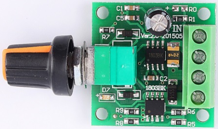
UPDATE 26/05/17: Having now blown these LMs- I've obtained a couple of 1803BK PWM controllers instead which appear to be better quality than the LM317s. I'm unable to get a schematic of these but I can tell you the spec (the large cap says 25v 100uF and the pot is 100K ohm if that helps):

Model: 1803BK - Ver2.0 201505 Input 1.8V-15VDC Max output: 30W Max output current: 2A Self-recovery fuse (2A) Duty cycle 0-100% (built in switch)

1803BKv2

The updated question now is, should I still apply the advice given below (1N4001 diode and 1000uF capacitor per controller) for this new setup? Also, as I have switches before the controllers, is it safe to leave them turned up before switching on - or would the sudden jolt of voltage/drawn current be damaging? I really don't want to blow these somewhat cute 1803s.

\$\endgroup\$
6
  • 1
    \$\begingroup\$ We need a schematic. There's a button on the editor toolbar and it's very simple to use. Double-click components to set their properties. When drawing the schematic try to keep positive rail on top, negative on bottom and reading left to right with current flow top to bottom. Welcome to EE.SE. \$\endgroup\$
    – Transistor
    Commented Jul 12, 2016 at 16:11
  • \$\begingroup\$ In theory, yes. The specifics of your motors and circuit will determine if it's possible in practice. A LM317 setup may not be the best. Specs for the motors? Current/Voltage? Power Supply capabilities? \$\endgroup\$
    – Passerby
    Commented Jul 12, 2016 at 16:15
  • \$\begingroup\$ OK, high-level block diagram provided. Now provide a schematic of what's inside "Linear DC Regulator" boxes. We can't guess. \$\endgroup\$
    – Transistor
    Commented Jul 12, 2016 at 18:25
  • \$\begingroup\$ What sort of heatsink was fitted to the LM317s? \$\endgroup\$
    – user16324
    Commented Jul 12, 2016 at 19:21
  • \$\begingroup\$ A small aluminium heatsink about the size and shape of a pencil sharpener. \$\endgroup\$
    – Mark
    Commented Jul 12, 2016 at 19:22

2 Answers 2

1
\$\begingroup\$

Here's the circuit of your regulator board (found here):-

enter image description here

This is a poor design. Input bypass capacitor C1 is the minimum size required to maintain regulator stability. A large electrolytic capacitor should be connected across the power supply input to handle surge currents, particularly if using long wires.

The recommended value for feedback resistor R2 is 240Ω. A slightly larger value will still work, but 1K is pushing it. This may explain why the specifications say minimum current draw is 5mA (since normally the 240Ω resistor does this).

They also say maximum current draw is 1.5A, but that is a lie. At 1.5A the LM317 drops 2.25V minimum, so the lowest possible power dissipation is 2.25V * 1.5A = 3.4W. When regulating a higher voltage at this current it would get burning hot in seconds and shut down.

Your motors may only draw 250mA when running, but the starting current could be 5 times higher. If your power supply is able to handle this the voltage may still sag as the motor starts up. This is another reason for using a large filter capacitor across the regulator input.

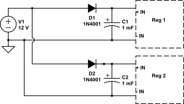
With two motor going at once you may get interaction between them as one effects the power supply of the other. If this is a problem then you could try isolating them with a diode in each positive supply lead, like this:-

schematic

simulate this circuit – Schematic created using CircuitLab

The purpose of the diodes is to prevent voltage sag caused by one motor from discharging the capacitor on the other motor.

\$\endgroup\$
2
  • \$\begingroup\$ So, between switch and reg a 1N4001 on + and 1 microfarad capacitor bridging + and -. Got it. Thanks. \$\endgroup\$
    – Mark
    Commented Jul 12, 2016 at 20:31
  • \$\begingroup\$ Yes, but that's actually a 1000uF capacitor (stupid CircuitLab insists on changing the units to millifarads). Use 16V or higher voltage rating. The diode can be placed anywhere in the individual supply lead for that regulator, eg. directly after the switch (which for simplicity I didn't show). \$\endgroup\$ Commented Jul 12, 2016 at 20:39
0
\$\begingroup\$

The answer is a qualified yes. Linear regulators provide a fixed voltage at the load current, and your 12 volt consumer unit provides 12 volts at the load current. If you are running your motor at 5 volts ands 250 ma you are operating your motor at 1.25W. Your supply is delivering 4 W, so 2.75 are heating up your regulator.

If you have a good enough heat sink, I would only suggest an addition of a diode (back biased) between pins 2 and 3 of your LM317 to protect against reverse voltage if you power down with the motors running, and addition of an RC between your voltage divider and pin 1 to prevent the regulator trying to compensate for motor noise.

Good choice going with a PWM instead of a series regulator; your power dissipation problems should go away. The 1n4001 is only a one-amp diode and not really necessary. Capacitance on the power supply side doesn't hurt and might help.

The real worry running multiple PWM's on the same line is oscillation when they are both running. The issue is that pulse-width modulation means that the voltage on the input is cycled on and off and the percentage of time it is on (called duty cycle) causes the average of the output voltage to rise (for higher percentage of on-time) or fall (for lower duty cycle). The averaged output voltage is sensed by the circuit and the duty cycle is constantly adjusted to keep the output voltage at the desired value (feedback).

What this means is that if the input voltage increases, the duty cycle must decrease to keep the output voltage constant. The current also decreases so this is the opposite of a resistive load, where the current increases if the voltage increases.

If you have two controllers on the same power line, when one is running and the second one kicks on, the voltage on the line will drop and the first controller's duty cycle (and current) will increase, causing a further voltage drop. Low frequency oscillation can occur if the two controllers alternatively pull the line down and then the current drops.

One solution is to use a large enough wire gauge to prevent the line voltage from dropping, but if you have a stable power source, the best and probably cheapest solution is to run a separate wire from each controller all the way back to the power source.

As far as the switch goes, it's hard to say without knowing the start-up characteristics of the controller, but I would put it on the power supply side just as you propose.

\$\endgroup\$
1
  • \$\begingroup\$ As the LM is an inefficient design, would any PWM controller be better or would it still need the diode/cap solution? \$\endgroup\$
    – Mark
    Commented May 30, 2017 at 15:30

Your Answer

By clicking “Post Your Answer”, you agree to our terms of service and acknowledge you have read our privacy policy.

Not the answer you're looking for? Browse other questions tagged or ask your own question.