0
\$\begingroup\$

Circuit storing number as binary Keypad[![Storing the number as binary]2
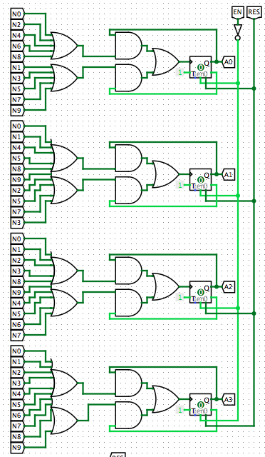
My aim is to store numbers from 0-15(4 bits) as binary. The numbers are inputted using a keypad with buttons labelled N0-N9. The circuit works for single digit numbers(0-9). But I don't know how to make it work for numbers 10-15. I also want to use two 7-segment displays to display the numbers inputted from the keypad. Initially, the display shows "00". If a single-digit number like 4 has to be inputted, the display reads "04". If a two-digit number like 13 has to be inputted, the display first reads "01" when 1 is pressed and then "13" when 3 is pressed. If a number greater than 15 is inputted(overflow), "NA" or something should be displayed.

\$\endgroup\$
7
  • 1
    \$\begingroup\$ the name is "Encoder" or "Priority Encoder". \$\endgroup\$
    – Eugene Sh.
    Commented Jul 22, 2016 at 19:26
  • \$\begingroup\$ What does the keypad output look like? \$\endgroup\$
    – EM Fields
    Commented Jul 22, 2016 at 19:44
  • \$\begingroup\$ EM Fields- Just two 7-segment displays. Can you help me out displaying two-digit numbers? \$\endgroup\$ Commented Jul 22, 2016 at 20:40
  • \$\begingroup\$ If you want to display double digit numbers and check that they are less than 15 only w/logic gates you will need some flip flops and a ton of logic gates. Is this for educational purposes, or you just despise micros? \$\endgroup\$ Commented Jul 22, 2016 at 22:15
  • \$\begingroup\$ I can, but if you want to get my attention, you must write "@EM Fields" somewhere in your post, so the system will ping me with your message. If you don't, then I must search to find you, which is a reversal of roles. Your comment makes no sense, since it seems that what you want to do is press the the keypad buttons twice and have the display register, in decimal, those digits, and render them as binary for some other purpose. Am I right?" \$\endgroup\$
    – EM Fields
    Commented Jul 22, 2016 at 22:32

2 Answers 2

1
\$\begingroup\$

Use 2 74LS148 or 2 74HC148 priority encoders, which drive a quad nand gate (74HC00) to get your 4 bit output. The inputs are active low, and so are the outputs, hence the need for the nand gates.

Wire the 'EI' input of the msb (the IC with inputs 8-15) to ground, and the 'EO' out to the 'EI' input of the next stage, which is the 0-7 inputs. The nand gates sum the 3 bit outputs and use the 'EO' output of the msb to drive the 4th nand gate, the msb of 4. The unused pin of gate 4 should be tied to logic 'High'. Now you have 3 IC's to get the output you want.

EDIT: To convert this binary output (which is not latched) to decimal requires a simple PIC MPU and the LED type number displays. If you can find an old TIL311 hexadecimal display on the market it will give you the hex value at the nand gate outputs.

The decimal display requires software to convert to decimal format, first latching in the newest hex value entered, then convert to a format compatible with the LED's, or you can output 2 BCD values and have them drive 2 7447 or 74LS47 BCD to 7-segment LED number displays.

You would need 10 to 15 IC's to latch, compare, convert to decimal then 7-segment LED drive output. With software you only need 1 to 3 IC's to do the same.

\$\endgroup\$
2
  • \$\begingroup\$ I am trying to build entirely on logic gates. Priority encoders can be implemented with NAND gates? \$\endgroup\$ Commented Jul 22, 2016 at 20:36
  • \$\begingroup\$ @DivyamKhandelwal. The 74LS148 series is a cluster of many gates. Google the part number and you will see how much it does. Using individual gates would fill up a large board and take much time. If you want primitive logic use the diodes as shown by Andyaka. The diodes are 1N4148's. \$\endgroup\$
    – user105652
    Commented Jul 22, 2016 at 20:42
0
\$\begingroup\$

If all you have is diodes and resistors and speed isn't important you can use this method: -

enter image description here

32 diodes and four resistors seems excessive this day and age but it was certainly done this way decades ago.

Alternatively use a 4 x 4 matrix keypad: -

enter image description here

The beauty about this is that you get a positive indication that "zero" is pressed. On the other hand just buy a keypad with a binary output (diodes incorporated).

\$\endgroup\$
5
  • \$\begingroup\$ 74C922 and 74C923 are obsolete parts but maybe Ebay has some left. I wish I would have stocked up with a tube of them myself. \$\endgroup\$
    – user105652
    Commented Jul 22, 2016 at 20:16
  • \$\begingroup\$ @Sparky256 try digipart: digipart.com/part/74C922 \$\endgroup\$
    – Andy aka
    Commented Jul 22, 2016 at 20:21
  • \$\begingroup\$ Thanks for the tip. They do cost ten times their original price though. I guess now-days your expected to just buy a MPU to handle keyboard inputs. Hexadecimal keypads are becoming rare as well. \$\endgroup\$
    – user105652
    Commented Jul 22, 2016 at 20:34
  • \$\begingroup\$ I am looking to build my project only with logic gates/basic components. The first method seems nice. Any other alternative methods you could help me with which use only logic gates? \$\endgroup\$ Commented Jul 22, 2016 at 20:43
  • \$\begingroup\$ I'm not going to recommend any method I wouldn't use so use a micro . \$\endgroup\$
    – Andy aka
    Commented Jul 23, 2016 at 0:27

Your Answer

By clicking “Post Your Answer”, you agree to our terms of service and acknowledge you have read our privacy policy.

Not the answer you're looking for? Browse other questions tagged or ask your own question.