1
\$\begingroup\$

schematic

simulate this circuit – Schematic created using CircuitLab

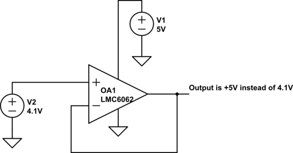
I'm using a precision OP AMP LMC6062AIM as a buffer (Voltage follower). The supply is +5V and GND.

The INPUT is a DC voltage (no modulation). If this voltage gets within 1V of the High Rail (so bigger than 4V or about), the output of the OP AMP goes to 5V (the rail). Also tried raising the supply to 7.5V and just like before, at 6.5V Input, the Output goes to the rail.

I've never seen this phenomenon before. I tried the same setup with a similar OP AMP (LMC6482) and this doesn't happen. It works as expected.

Anyone how any idea why this happens, or how it can be corrected?

\$\endgroup\$
2
  • \$\begingroup\$ Can you post a schematic? Have you simulated in LT-Spice? \$\endgroup\$
    – Tyler
    Commented Jul 25, 2016 at 13:33
  • \$\begingroup\$ Classic problem. Get yourself a rail-to-rail opamp. Please note that an op-amp can be rail-to-rail on the input and/or output so read the fine print in the data sheet. \$\endgroup\$
    – winny
    Commented Jul 25, 2016 at 17:32

2 Answers 2

6
\$\begingroup\$

Look at the datasheets!

The LMC6062 datasheet says on page 3:

Input common mode voltage range: \$0..V^+\$ − 2.5V

i.e. at \$V^+ - 1V\$ you are already 1.5V above the range that is guaranteed to work.

The LMC6482 datasheet on the other hand says it is a rail-to-rail input and output OpAmp, i.e. it works with input voltages from GND rail (0V) to up to the \$V^+\$ rail.

\$\endgroup\$
3
\$\begingroup\$

Basically, you are exceeding the CMIR ("Common Mode Input Range") of the LMC6062. In general, you should keep voltage on the inverting and non-inverting inputs of an op-amp within this specified operating range. Strictly speaking, a particular model op-amp is only "guaranteed" to operate within this range of input voltages.

In most cases a transgression of input voltage beyond the CMIR is benign. However, in some op-amps the results of such a over-voltage condition can be quite unexpected. Some op-amps will actually reverse the output polarity under these conditions. That is, instead of the output going to the positive rail as in your example, the output will actually flip over and go to the negative rail! Such actions can bewilder the unwary beginner. Seasoned designers will know exactly what is happening.

The prevention is to not allow your input voltage to go beyond the common mode input range. There are various ways to accomplish this. The simplest and most common way is to use a diode limiting topology. This is not very precise and may cheat your design of some useable CMIR range. Better precision can be achieved with more complex schemes. Which you choose will depend on the usual design tradeoff of cost, space, etc.

\$\endgroup\$

Your Answer

By clicking “Post Your Answer”, you agree to our terms of service and acknowledge you have read our privacy policy.

Not the answer you're looking for? Browse other questions tagged or ask your own question.