0
\$\begingroup\$

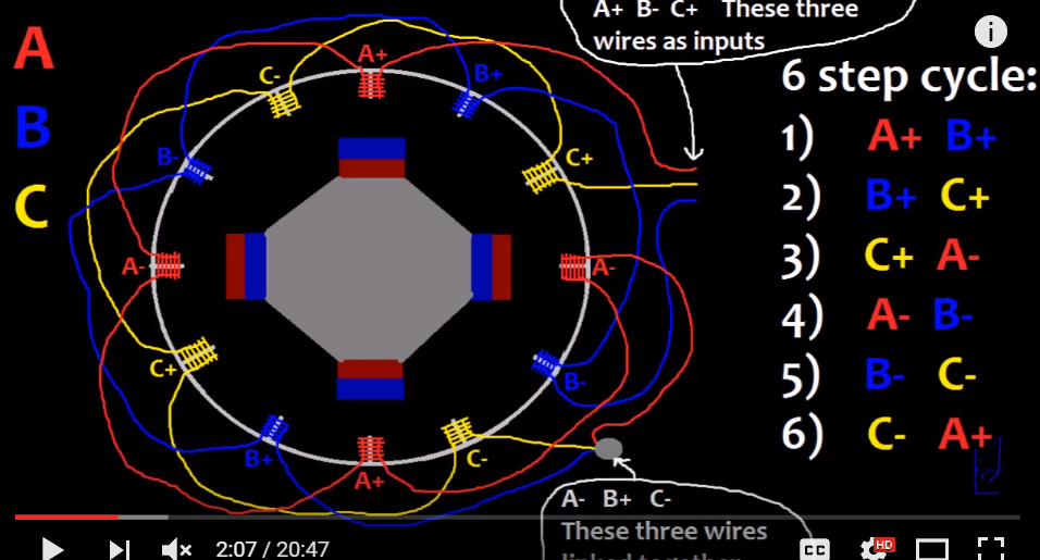
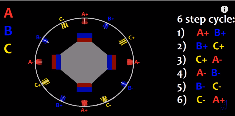
I was trying to make a generator out of a DC motor inrunner by following this video by following this schematic: 1 enter image description here
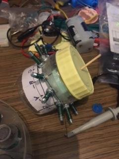
I made this structure and started testing the phase voltages. A-, B+, C- are combined together and made as the neutral wire. enter image description here
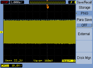
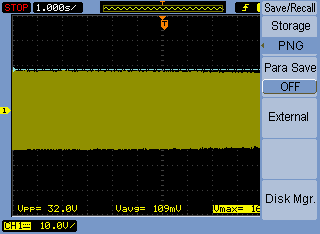
While testing the voltage outputs from A_neutral, B_neutral, C_neutral, V_ab, V_bc and V_ac, I am getting non-uniform outputs and I am getting problems troubleshooting this issue.

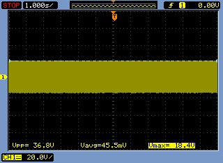
Voltage_cb

Voltage_cb

Voltage_ab

Voltage_ab

Voltage_ac

Voltage_ac

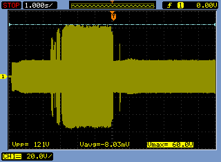
Voltage_a_with_neutral

Voltage_a_with_neutral

Voltage_b_with_neutral

Voltage_b_with_neutral

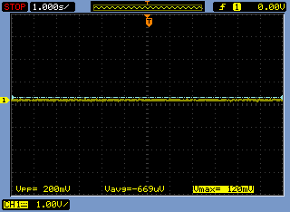
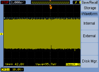
Voltage_c_with_neutral (almost no voltage, dont know why)

Voltage_c_with_neutral (almost no voltage, dont know why)

Why is the voltage_cneutral almost nil compared to the other voltages? I checked the copper coil winding and they are all same.

\$\endgroup\$
9
  • \$\begingroup\$ Most of us won't watch a video link. (1) Add a schematic using the button on the editor toolbar. (2) Explain what "inrunner" means. (I never heard of it.) (3) Explain the change in voltage on the a-N trace. \$\endgroup\$
    – Transistor
    Commented Aug 3, 2016 at 7:14
  • \$\begingroup\$ Thanks, I have updated. Although I am not ale to explain the change in the voltage on the a-N trace, I was moving around the wires for adjustment which caused a big surge. I still have not understood. \$\endgroup\$ Commented Aug 3, 2016 at 7:20
  • \$\begingroup\$ You don't have a neutral, you don't need a neutral. Where did your neutral come from??? Maybe your neutral is the problem?? You only need to rectify the 3 phases with 6 diodes, no neutral in sight. Look up '3 phase full wave recitifier'. \$\endgroup\$
    – Neil_UK
    Commented Aug 3, 2016 at 7:23
  • \$\begingroup\$ (1) You still haven't explained "inrunner". (2) There is no neutral on those wiring diagrams. \$\endgroup\$
    – Transistor
    Commented Aug 3, 2016 at 7:24
  • \$\begingroup\$ @Neil_UK A-, B+ and C- are soldered together and made as neutral \$\endgroup\$ Commented Aug 3, 2016 at 7:33

1 Answer 1

1
\$\begingroup\$

It seems like you have a loose connection somewhere. With magnet wire, you need to carefully scrape the varnish off the surface of the wires, twist them together and solder them. The voltage A to neutral trace shows the voltage jumping up and down. That must be the result of a loose connection. The scope patterns seem to be inconsistent with one another. It appears that moving the scope probes may move the wires so that the connections change.

\$\endgroup\$
1
  • \$\begingroup\$ I found the problem, it was giving inconsistent output because of main line interference similar to this. \$\endgroup\$ Commented Aug 4, 2016 at 10:25

Your Answer

By clicking “Post Your Answer”, you agree to our terms of service and acknowledge you have read our privacy policy.

Not the answer you're looking for? Browse other questions tagged or ask your own question.