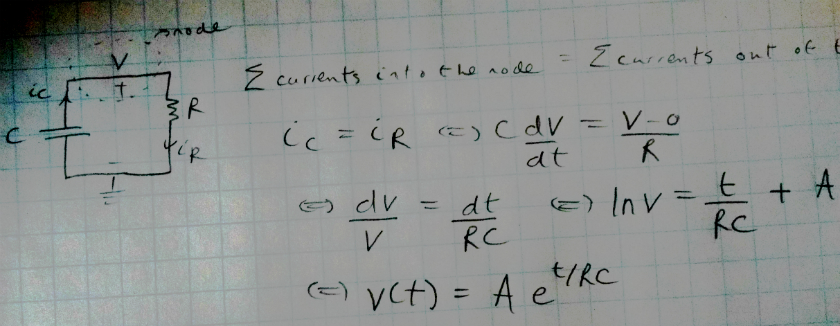
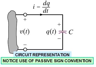
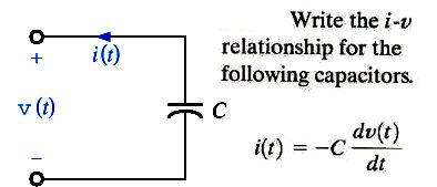
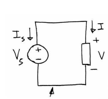
I made the same mental mistakes all the time, too. Rather than being very careful about direction (and therefore sign), I'd just toss the salad together. Partly, because I had so much confidence in mathematics, generally. Over time, I've not unlearned that rash behavior. But I've supplemented it with taking time to cross-check myself, later. And, to being able to recognize when a result is silly on its face, when I get such a result, and to go back and recheck the signs, again.
So this is where rigor comes in and gut instinct needs a harness of sorts.
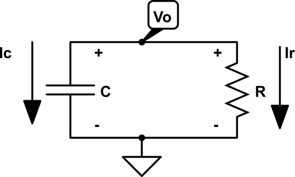
Here's how I'd lay out the schematic you are analyzing, on paper:
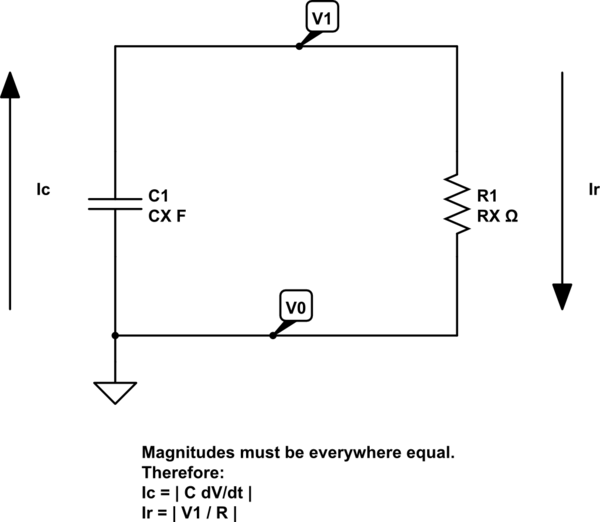
simulate this circuit – Schematic created using CircuitLab
So. What now? Well, the rules are that charge isn't allowed to collect in a node. That's basic physics. If much charge (and it's not much) is allowed to accumulate in a node, you could move heaven and earth with it. It's that powerful. You also know that when you sum voltages around any loop, that you should get back to where you started, in the end.
It is very tempting to look at those arrows and to imagine that it's all part of a circle of current, so it must be the same current so it must also be the same sign. So if one is positive, the other must be. Or if one is negative, so must also the other be. But that's where you get into trouble. The rule here is NOT that a circle of current always has the same sign! Mentally, it sure seems that way. But that is a very slippery slope and it is really just a mental short-cut that, this time, gets you into trouble.
The physical principle to apply is that charge doesn't sum into a node. A node is always neutral. So all of the incoming current must be equal to all of the outgoing current. You can pick any node you want and that rule remains true. Nature simply doesn't allow much charge to accumulate and, where it does, one has to work very hard to make something able to hold even very tiny amounts. (Capacitors, obviously.)
So now the rigor comes in. Let's start out doing this simply. We know the following must be true about accumulating charge at the node:
\$Q_1\left(t\right) = 0, Q_0\left(t\right) = 0\$
Therefore, thinking about the rate of change of charge at the node:
\$I_1\left(t\right) = \frac{d Q_1\left(t\right)}{dt} = 0, I_0\left(t\right) = \frac{d Q_0\left(t\right)}{dt} = 0\$
Pretty basic stuff. This just means that the net current into/out of either node is always \$0A\$. That's not a surprising result. It's also obvious from a basic physical understanding.
Now, let's use the above and plug in your mental assumptions about the circulating current and see where that takes us:
\$I_1\left(t\right) = 0 = I_c + I_r\$
Now you face a profound problem in your earlier mental thinking process. If the above equation is true (and it is) and if it is also assumed to be true that \$I_c = I_r\$, then the only possible solution set for the above equation is if \$I_c = I_r = 0A\$. But you already know that isn't true. You are talking about a real situation where there will actually be a non-zero current -- though changing.
So it then follows (given the variable definitions so far) that \$I_c \ne I_r\$ and, in fact, that from \$0 = I_c + I_r\$, we must get \$I_c = -I_r\$ if \$\vert I_c\vert = \vert I_r\vert\$. It's the only possible solution. And that's now obvious.
Of course, this would have been obvious right away had you been focused only on the node called \$V_1\$ and realized that the incoming current into that node must have the opposite sign of outgoing current from that node.
Regardless of how you get there, things are now clearer. We must have:
\$I_c + I_r = 0 = C\cdot\frac{dV_1}{dt} + \frac{V_1}{R}\$
And by inspection we can easily see that while \$V_1\left(t \ge 0\right) \ge 0V\$ and therefore that \$\frac{V_1\left(t \ge 0\right)}{R} \ge 0A\$, it must then be true that \$\frac{d V_1\left(t \ge 0\right)}{dt} \le 0\$. And when you think about it, then you realize that of course it must be that the voltage at \$V_1\$ is declining and that therefore the sign of the change is negative. It all just comes together as clear and obvious, if it wasn't beforehand. Just let \$V = V_1\$:
\$C\cdot\frac{dV}{dt} + \frac{V}{R} = 0\$
\$R\cdot C\cdot\frac{dV}{dt} + V = 0\$
\$R\cdot C\cdot dV = -V\cdot dt\$
\$\frac{dV}{V} = -\frac{dt}{R\cdot C}\$
\$\int \frac{dV}{V} = \int -\frac{dt}{R\cdot C}\$
\$ln\left(V\right) = -\frac{t}{R\cdot C} + c_0\$
\$V = e^{-\frac{t}{R\cdot C}} \cdot e^{c_0}\$
\$V\left(t\right) = A_0\cdot e^{-\frac{t}{R\cdot C}}\$
And of course we need to get \$A_0\$ from initial conditions, when \$t=0\$. Clearly, \$A_0\$ is just the initial voltage on the capacitor \$C_1\$.

