6
\$\begingroup\$

The bypass capacitors are used for example to filter out noise at the power supply of an IC. Usually 2 or more capacitors are applied in parallel to cover wider range of frequencies.

However, I have learned about 3-terminal capacitors that have extremely low ESL and therefore cover much wider range of frequencies than usual by pass caps. As I see it, instead of several bypass capacitors one cold use single 3-terminal capacitor. However, since I had never seen the 3-terminal capacitors in such role, I assume there are pitfalls that I am not aware of. What are they?

And what the 3-terminal caps are used for then?

\$\endgroup\$
3
  • \$\begingroup\$ Mechanical stability. If you want low ESL, you want strip or foil connection. \$\endgroup\$
    – winny
    Commented Oct 25, 2016 at 12:59
  • 2
    \$\begingroup\$ Price, of course. \$\endgroup\$
    – CL.
    Commented Oct 25, 2016 at 13:12
  • \$\begingroup\$ This topic of the 3-terminal capacitors is of great interest for me, too. Did you find any more information? Did you decide to use them is your design? Do you have any more experience with them? \$\endgroup\$
    – nickagian
    Commented Jun 20, 2017 at 6:21

2 Answers 2

3
\$\begingroup\$

instead of several bypass capacitors one cold use single 3-terminal capacitor.

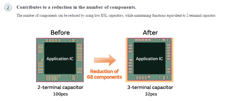
In fact, Murata recommends them for exactly that application:

enter image description here

However you might find that, due to using more vias per capacitor, these parts take up more board space than you expect.

Also, you will be locked in to buying a fairly high-priced from Murata, rather than a commodity part you can shop around for.

\$\endgroup\$
2
  • 1
    \$\begingroup\$ Fortunately, Murata is not the only manufacturer. And don't cost that much especially if the cost of tantalum caps that are usually used for low frequencies are counted in: mouser.de/Passive-Components/Capacitors/Feed-Through-Capacitors/… So is it advisable to use them in place of common 2 terminal bypass caps? \$\endgroup\$
    – Andrey Pro
    Commented Oct 25, 2016 at 18:59
  • 1
    \$\begingroup\$ @AndreyPro, the highest value available seems to be 10 uF. You will probably still want some bigger values (whether electrolytic, tantalum, or ceramic) on your board. \$\endgroup\$
    – The Photon
    Commented Oct 25, 2016 at 19:28
0
\$\begingroup\$

I'd advise avoiding the use of such combination capacitors for the purpose you described. They are best used to save some space in cases where identical capacitor types are needed. For example, if you were building a "brute force" DC power supply with a "Pi" filter, and needed two similar caps with an inductor bridging the two.

The reason for multiple capacitors in the kind of circuit you described is usually to use different types of capacitors, each one doing the job they individually do best. A simple example might be a 500uF electrolytic capacitor in parallel with a 0.1 uF ceramic disc capacitor. The ceramic disk cap will respond much more quickly to fast transients, while the larger electrolytic would provide better filtering of slower supply ripple. While you might get one dual capacitor with different values, I've not seen any in which the two elements are of completely different dielectric types. They may exist for just the purpose I described, but I suspect you'd find the "old fashioned" way of using separate caps to be a cheaper solution.

\$\endgroup\$
1
  • \$\begingroup\$ The three-terminal capacitors the OP is referring to are actually single ceramic capacitors - not at all like the old multi-section electrolytics - see the Murata article the OP linked to. \$\endgroup\$ Commented Oct 25, 2016 at 16:06

Your Answer

By clicking “Post Your Answer”, you agree to our terms of service and acknowledge you have read our privacy policy.

Not the answer you're looking for? Browse other questions tagged or ask your own question.