3
\$\begingroup\$

I know theory about decoupling capacitors (ESR, ESl, parallel capcitors etc.) I have read Electromagnetic Compatibility Engineering, H.W. Ott. My question is about practical design. How shall i choose appropriate capacitors to achieve the best results ?

I have to design mixed signal pcb. It is measurement system with analog front-end, ADC, DAC, FPGA. There will be a few chips which will be working with different frequencies (shall I take into consideration each freq?).

Do engineers in this type of design calculate capacitors carefully (taking into considerations for example impedance peaks in resonance frequency) or put a few different range capacitors ?

I would like to solve this problem in correct way not only for the best system accuracy but also for knowledge for the future deign :)

Could I kindly ask more experienced people for an advises and answers ?

Cheers, e2p

\$\endgroup\$
2
  • 2
    \$\begingroup\$ We're in luck, Dave from the EEVBlog has made an excellent video about this subject, see: youtube.com/watch?v=BcJ6UdDx1vg \$\endgroup\$ Commented Nov 21, 2016 at 16:00
  • \$\begingroup\$ I saw this video, it is great but I don't know how to calculate appropriate parallel capacitances for many frequencies. Shall I just put 10uF, 1uF, 100nF, 10pF or calculate it carefully for each chip. \$\endgroup\$
    – e2p
    Commented Nov 21, 2016 at 16:03

5 Answers 5

2
\$\begingroup\$

Normally when I do a design I use the decoupling capacitor recommended by the manufacturer datasheet. No deep analysis is usually involved.

In cases where I am doing something more custom I use a great web based tool called K-SIM.

http://ksim.kemet.com/

In its simplest use, it can calculate the impedance, and ESR of a capacitor across frequency.

Given a set of real ceramic capacitor part numbers, and the quantity of each part, it can calculate the impedance of the set of capacitors in parallel across frequency. It takes into account the non-ideal properties of the capacitor when doing the calculation.

It can also do other calculations such as ripple current, temperature rise, S-parameters, etc.

\$\endgroup\$
3
\$\begingroup\$

It depends upon the application. For very sensitive applications you could do all of that.
Most of the time checking the datasheet for the manufacturers recommendations is good enough.

If in doubt 1x 100nF per power pin plus a single 10uF near any larger parts/processors and you'll be good for most designs.

There is a very good reason for sticking to a simple rule like that, when it comes to manufacturing you pay for the setup time on the pick and place machine. It's a lot quicker and simpler to load 1 or 2 reels of capacitors than to load 20 different reels because each IC needs different value caps.

\$\endgroup\$
1
  • \$\begingroup\$ One tip is that if a part draws a lot of power off the same pin (some pin-constrained digital parts like fast SRAMs are this way), use two 100nF caps on the power pin. \$\endgroup\$ Commented Nov 22, 2016 at 12:37
1
\$\begingroup\$

For mixed signal designs, layout and placement is generally far more critical than the specific decouplers used, although manufacturers will often state a decoupling scheme if they believe it to be critical.

The rule of thumb (as already noted) is 100nF per power pin and a bulk decoupler for larger components (such as processors, microcontrollers, large FPGAs).

Xilinx goes into quite some detail on this subject.

\$\endgroup\$
0
\$\begingroup\$

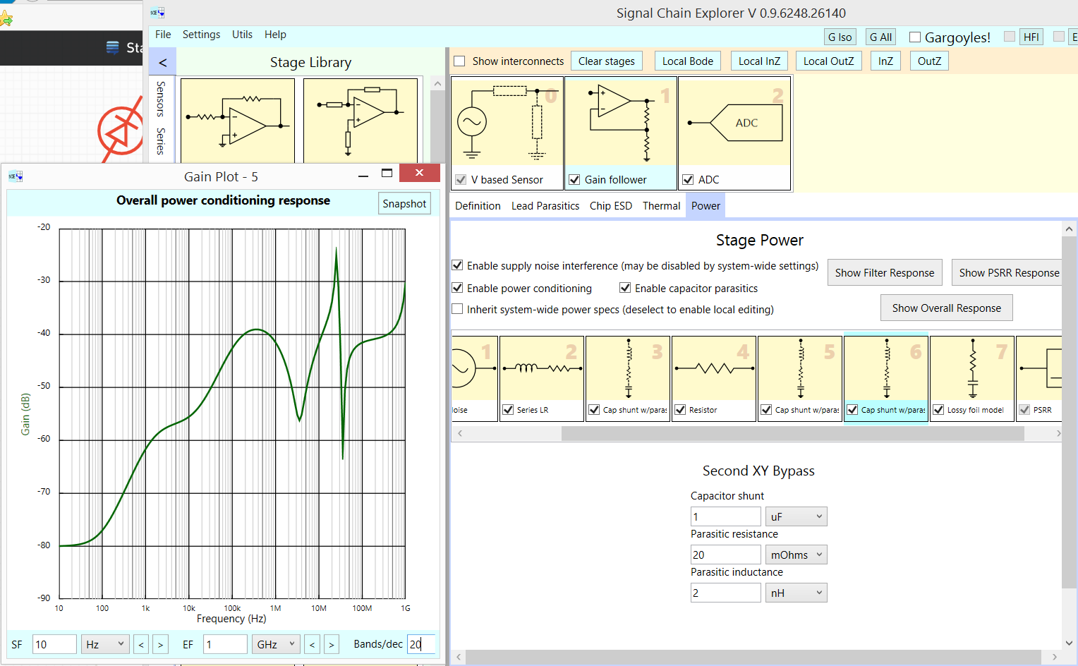
Capacitors in parallel WILL RESONATE. You need to identify those peaks (and valleys) and intentionally pick lossy dielectrics or insert dampening Rs. The first screenshot shows the valleys and peaks for 100uF and 0.01uF and 1uF. The final capacitor[20 pF] uses SkinEffect for dampening.

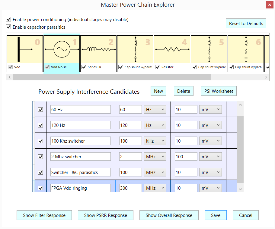
Use the free tool Signal Chain Explorer, in the "Gargoyles" mode. And click on ONLY the PSI {power supply interference} button. Then examine that PSI database (table of interferers) to ensure the 60Hz and 120Hz and SwitchReg and FPGA interferers are enabled. SCE is downloadable from robustcircuitdesign.com

The default topology is just a sensor and ADC. Click on Sensor, then go to left margin, select "amps" and select the amplifier stage closest matching your needs. Double click to insert. Double click again, for a 2nd gain stage. Edit the opamp specs (Unity Gain BandWidth & Rout in particular). Edit the Rg and Rf to set gain. Click "Update" on top right, and you'll see the SNR and ENOB predicted by the tool at specific FOI frequency-of-interest. Edit the "Sensor Stage" for voltage.

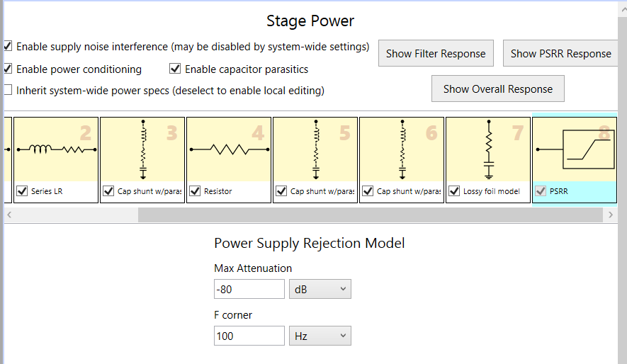
And edit the Power Supply Rejection params {corner freq and Max Atten}

This is what you will see, for "filtering"

enter image description here

and this is the PSI database (you can edit or add your own interferers)

enter image description here

and here is how to edit the Power Supply Rejection params for any OpAmp stage.

enter image description here

Click "analysis details" for text window analysis of the many contributors to Code Spread.

\$\endgroup\$
0
\$\begingroup\$

We like small MLCCs for low inductance and low price. Low inductance is desirable for HF decoupling. However,

  • Inductance does not depend on cap value, only on package and mounting.
  • Value determines price

Let's consider a 4-layer (or more) board with a ground plane in one of the top layers, usually layer 2. Now, the power supply you want to decouple can either be:

  • a local supply with a local regulator for one sensitive analog chip with one or a few power pins

Unless it is BGA, the inductance of your chip's VCC pin and the track leading to it will usually be higher than the ESL of a properly mounted MLCC. Therefore, paralleling MLCCs will usually not improve inductance, but it will worsen resonance. Use the highest value MLCC in X7R that will fit in say, 0603 or 0805. Add bulk capacitance if needed to make regulator happy. If regulator datasheet boasts "stable with 1µF MLCC"... check output impedance with network analyzer, if it looks ugly then add some bulk capacitance...

A 10nF 0805 cap will have the same inductance as a 1µF 0805 cap. But the 0805 cap will store 100x more energy. Therefore, I'd use 1µF... and no 10nF in parallel!

Note: a precision opamp will not meet its settling time specs if its power supplies are polluted with large HF spikes due to caps resonating. HF PSRR of opamps isn't good.

  • traces feeding many chips

You will need one cap per chip at least, but those traces add inductance, and worsen resonance. Paralleling MLCCs with tracks is a bad idea. This will also inject noise into your GND as the caps resonate. Depending on circumstances, adding ESR can be beneficial. Think about 0R1 chip resistors. Simulate the network. If you use ferrite beads, remember they are inductors, you are making a LC network. Check the bead spice model, and adjust bulk cap ESR for damping.

  • (1) a power plane which feeds many chips

A plane will allow you to parallel many caps without (too much) resonance problems, provided they are properly mounted, values properly selected, etc.

Decoupling a plane is where you use those 10nF capacitors, in numbers, to reduce inductance.

Note about fancy low-ESR polymer caps. If you parallel one of those with a MLCC without proper care they'll resonate...

\$\endgroup\$

Your Answer

By clicking “Post Your Answer”, you agree to our terms of service and acknowledge you have read our privacy policy.

Not the answer you're looking for? Browse other questions tagged or ask your own question.