2
\$\begingroup\$

I am designing a hobby project that will run on a battery so I am trying to reduce power consumption. The SoC I am using has the ability to go into a deep sleep mode where it consumes very little power, and then can be interrupted by a falling edge on a pin.

I want to generate a high-low-high pulse when the state of a reed switch changes in either direction. I have been reading a lot and it seems that a one-shot monostable circuit can be built from a couple of transistors and an RC circuit to generate an output pulse when an edge is detected. I understand how that works. However, I can't figure out the best way to also pulse on the opposite edge.

One thought, was to just combine two one-shots that are configured to trigger on rising and falling edges respectively, and use the transistors at the output to pull the common pull-up low (kind of like a NOR gate).

Since I am a hobbyist, I am mostly using passive components. What is the "real" way of doing this in a low-power configuration using logic devices?

Edit: I figure I should mention something about the timing requirements. Normally the reed switch will be either open or closed for many seconds at minimum before changing states.

Edit: Here is an example of the circuit I was using for detecting only the falling edge:

Schematic

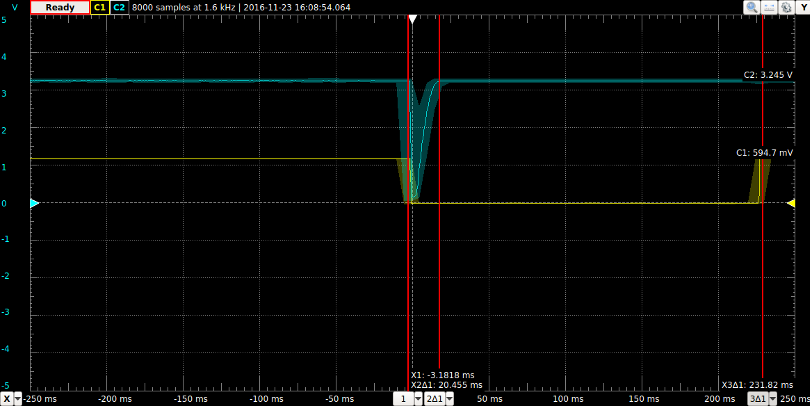
And here is the ~20ms pulse it was producing for ~200ms button press simulating the reed switch (Channel 1 is Vbe for T1 and Channel 2 is measured at RST):

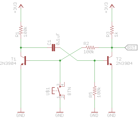
Scope of pulse response

\$\endgroup\$
1
  • \$\begingroup\$ I made a module for this (designed for use with ESP8266), since for various new projects, I find myself needing to wake the ESP8266 when sensor values change: github.com/nbolton/esp8266-dual-edge-wake \$\endgroup\$ Commented Jan 29, 2023 at 23:14

4 Answers 4

9
\$\begingroup\$

You are asking for a edge to glitch converter, which is usually a flag indicating a kludge. Are you really sure your SoC can't be configured to interrupt on either edge? This is a common feature of many microcontrollers. In PICs it's called interrupt on change, for example, and just about every PIC has a few inputs that are capable of it.

If your hardware can really only interrupt on a falling edge, then one possibility is to simply invert the signal and wire it into two such inputs.

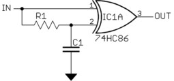
To answer your question directly, a edge to glitch converter can be made from a XOR gate:

OUT will be low as long as both inputs to the gate are equal. The signal into pin 2 is delayed a little by the R-C low pass filter. This means that for a short time after IN changes, pin 1 will have the new value and pin 2 the old value, which causes OUT to go high. After a short while, the pin 2 signal catches up and the output goes low again.

You can either use this to trigger on the end of the pulse, or use a XNOR gate to get a negative going pulse so that the leading edge will trigger the interrupt.

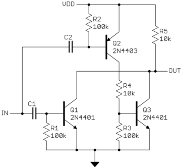
Since you said you are a hobbyist, here is a circuit that uses only junkbox parts:

This may look like a ratsnest, but is easy to understand if you break it down into individual pieces.

C1 AC-couples the input signal into Q1. Q1 will turn of for a little while due to a rising edge on IN. When it does, it forces OUT low. R5 is a passive pullup so that OUT is high when nothing is going on. That takes care of detecting a rising edge on IN.

Detecting the falling edge is done similarly with C2 and Q2. However, when Q2 turns on, it pulls its output high instead of the low you want. Q3 inverts that and pulls OUT low when Q2 is on.

\$\endgroup\$
4
  • \$\begingroup\$ A more complete answer might include the reed-switch input conditioning, which usually requires a pull-up or pull-down resistor to logic supply voltage. One of the spare gates might be used as a buffer, else the pull-up/pull-down resistor must be significantly smaller than Olin's "R1". Interrupt-on-change is the better solution. \$\endgroup\$
    – glen_geek
    Commented Nov 22, 2016 at 16:25
  • \$\begingroup\$ Yes AFAIK the SoC only interrupts on falling edge, and implements its own wake up from deep sleep by tying an output pin to reset, and setting that pin high for a set amount of time before falling and waking up the device. I will implement the "ratsnest" and see how it works for me! \$\endgroup\$
    – billbo
    Commented Nov 23, 2016 at 22:46
  • \$\begingroup\$ Curiously when I search for “MCU wake on edge”, it brings me to my EE SE question which is arguably a dupe of this question/answer… electronics.stackexchange.com/questions/649205/… \$\endgroup\$ Commented Jan 28, 2023 at 22:50
  • \$\begingroup\$ Does anyone know what search terms would lead me to an SoC that support wake from deep sleep on either edge? \$\endgroup\$ Commented Jan 28, 2023 at 22:51
5
\$\begingroup\$

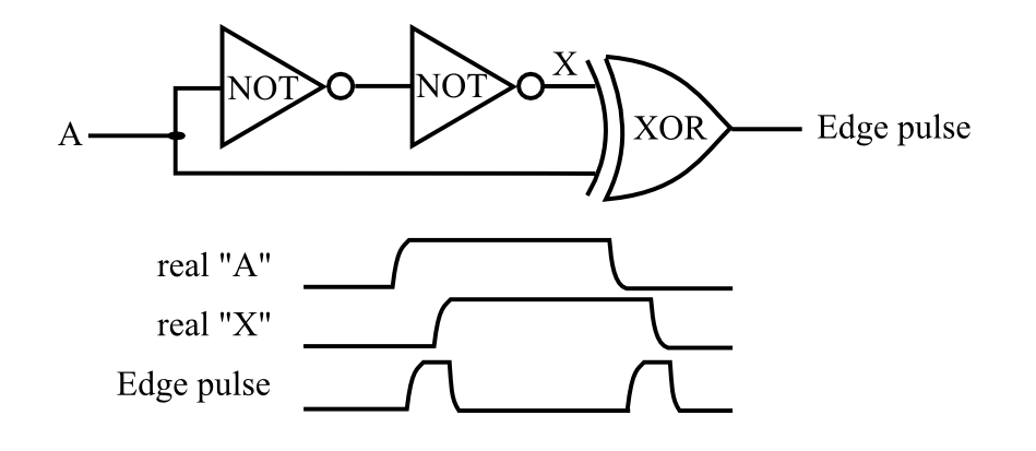
This XOR gate and delay circuit might work for you: -

enter image description here

I'd use a gate with a schmitt trigger input for reliability.

Or maybe a couple of inverters instead of the RC: -

enter image description here

Inverting the output is basically easy.

\$\endgroup\$
1
  • 1
    \$\begingroup\$ Yeah, the inverters+XOR solution can be implemented using 3/4ths of a 74xx86 for that matter (handy if you don't have the spare gates roaming around your board already) \$\endgroup\$ Commented Nov 22, 2016 at 23:48
1
\$\begingroup\$

dual edge detection one input pulsed

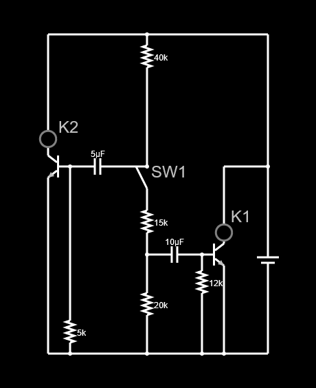
If you attach your reed switch at SW1, LEDs K1 and K2 are alternately pulsed. This circuit was designed for a very specific application and is for 9 volts, but some tinkering with the resistor and capacitor values should allow you to only turn the power for your unit on for the pulse duration whenever the status of the reed switch changes changes by wiring into the k1 and k2 transistor C and E.

\$\endgroup\$
0
\$\begingroup\$

Your initial idea seems good. I would avoid the flip flop idea but it is a perfectly valid solution (just maybe unnecessary).

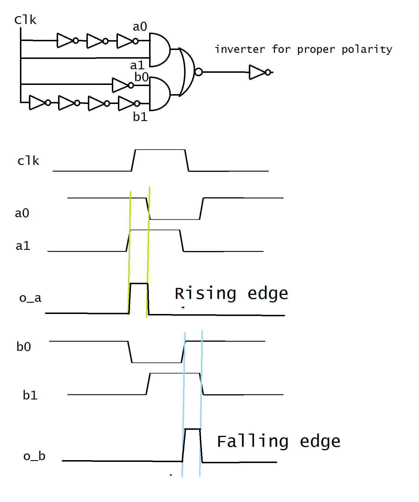
Typically this could be implemented easily with an AOI22 gate (single stage complex CMOS gate which implements !((A0*A1)+(B0*B1))

A0 and A1 would work to form a rising edge pulse detector, and B0/B1 to form the falling edge.

For rising edge, delay one input by an odd number of inversion stages (more inversions or more cap between stages means longer pulse). For the falling edge, invert one input once. Invert the other input an even number of inversion stages (again the more inversions you have or the more cap between each node causing delay, the longer the output pulse). It makes a lot more sense with the waveforms shown:

aoiedge detectors

It is worth mentioning that in this configuration the AOI22 acts as a XOR gate (due to polarity of inputs).

\$\endgroup\$

Your Answer

By clicking “Post Your Answer”, you agree to our terms of service and acknowledge you have read our privacy policy.

Not the answer you're looking for? Browse other questions tagged or ask your own question.