2
\$\begingroup\$

In the past I've tried to use 10nF (0.01uF) and/or 100nF (0.1uF) capacitors for decoupling ICs and micro-controllers.

However, I've heard that when using physically small capacitors (for example 0402), the capacitance of the capacitor doesn't affect the frequency response, and therefore it's best to just use the largest value you can get.

Therefore, I was wondering if it's a good idea for me to just buy a lot of 1uF capacitors in 0402 packaging and always use one of these going forwards (is 1uF too high?).

Specifically I was thinking about this one: http://datasheet.octopart.com/CL05A105KP5NNNC-Samsung-datasheet-26589000.pdf

It's 1uF, 10V and 0402, it also works up to 85 degrees celsius and is made by a brand I've heard of. It's also pretty cheap at 0.5 cents each.

I'm interested if there's any reasons I'd need other values, or if this is a good idea. Additionally, should I stretch to 5uF in 0402 size? Is there a limit? (I can't solder smaller than 0402.)

Thank you.

\$\endgroup\$
6
  • 3
    \$\begingroup\$ I suggest that you watch the EEVBlog episode about bypass caps: youtube.com/watch?v=BcJ6UdDx1vg watch it, it is good !!! \$\endgroup\$ Commented Feb 22, 2017 at 12:35
  • 2
    \$\begingroup\$ I would not recommend getting many 1uF (or higher) in 0402 for decoupling, I would consider 100 nF 0402 a much better choice as these will have better high frequency performance. In my opinion with 100 nF you would cover like 90% of all the decoupling needs. Only for very fast circuits I would consider adding a 100p F 0402 in parallel to the 100 nF. \$\endgroup\$ Commented Feb 22, 2017 at 12:38
  • \$\begingroup\$ why is the frequency response of a 100nF 0402 worse than a 1µF 0402? \$\endgroup\$
    – Christian
    Commented Feb 22, 2017 at 13:09
  • \$\begingroup\$ @Christian I think the video explains it fairly well. \$\endgroup\$
    – AngeloQ
    Commented Feb 22, 2017 at 13:17
  • 1
    \$\begingroup\$ "It depends !" There is way to much modeling that goes into choosing the capacitors. Since you probably can't model the IC package and have no knowledge of the internal capacitors in the package. I would suggest using the smallest package you can and don't use different capacitor values in parallel. Many times just trail and error is more effective than rigorously modeling everything. \$\endgroup\$
    – Mike
    Commented Feb 22, 2017 at 19:20

4 Answers 4

3
\$\begingroup\$

High frequency behavior (ie, inductance or ESL) of MLCC caps depends on:

  • Package shape and dimensions
  • Mounting inductance (ie, position of vias, etc)
  • And number of caps in parallel of course

Capacitance influences the self-resonant frequency of course, but only has a very small influence on inductance, mostly through making the package bigger.

The real reason to stick lots of caps in parallel between power and ground planes is to lower the inductance. In this case, usually small values are used like 10-100nF, because it's cheaper. This matters for a PC motherboard where you got hundreds of caps.

If you replace them with 1µF, it will cost a little more, but it will work just as well.

For DIY stuff, it does make sense to do what you suggest. Just get a hundred 1µF caps with quantity pricing, and off you go. Please note that the "1µF" is only with 0V bias though, and smaller packages tend to lose more capacitance under bias than larger ones like 0805.

Note: I am not covering the case where the capacitor self resonant frequency is used in the design.

\$\endgroup\$
1
\$\begingroup\$

Here is what you'll encounter with multiple caps:

enter image description here

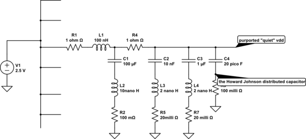
This is the local branch of a VDD_tree

schematic

simulate this circuit – Schematic created using CircuitLab

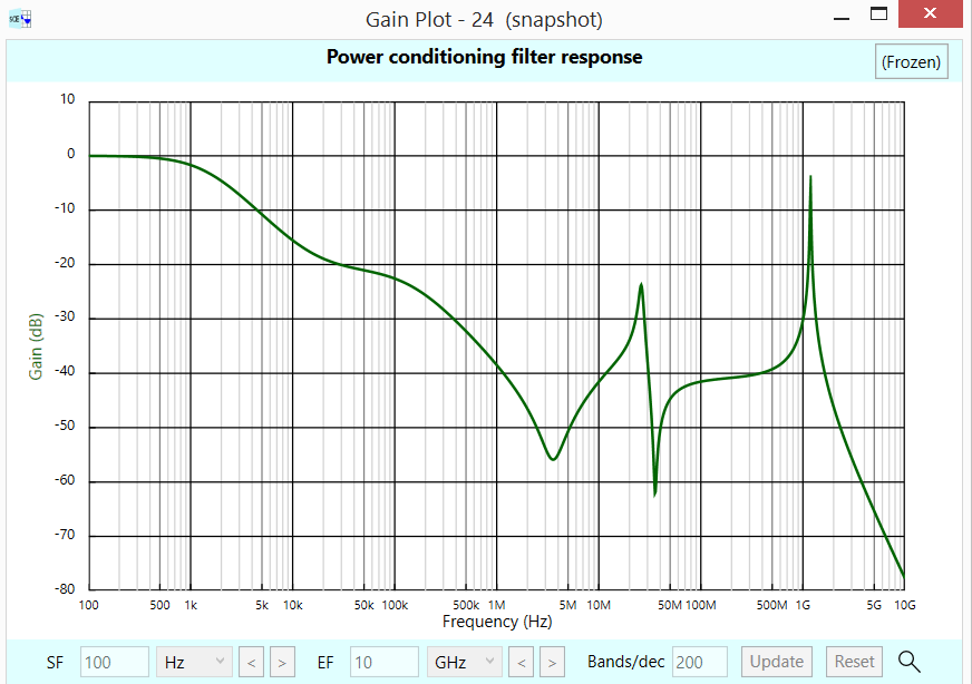
Again......multiple caps in parallel, even distributed across the planes, will resonate as in PI_FILTER_resonate. For smooth (less peaky) response, have a plan to dampen the peaks

(1) skin effect at the higher frequencies; at 500MHz (100X the SD of 1ounce foil), you get 10X thinner SD and a useful rise in foil losses to 5milliOhm per square; this value, 5 milliOhm/square hides many an oversight in planes

(2) lossy cap dielectric at lower frequencies

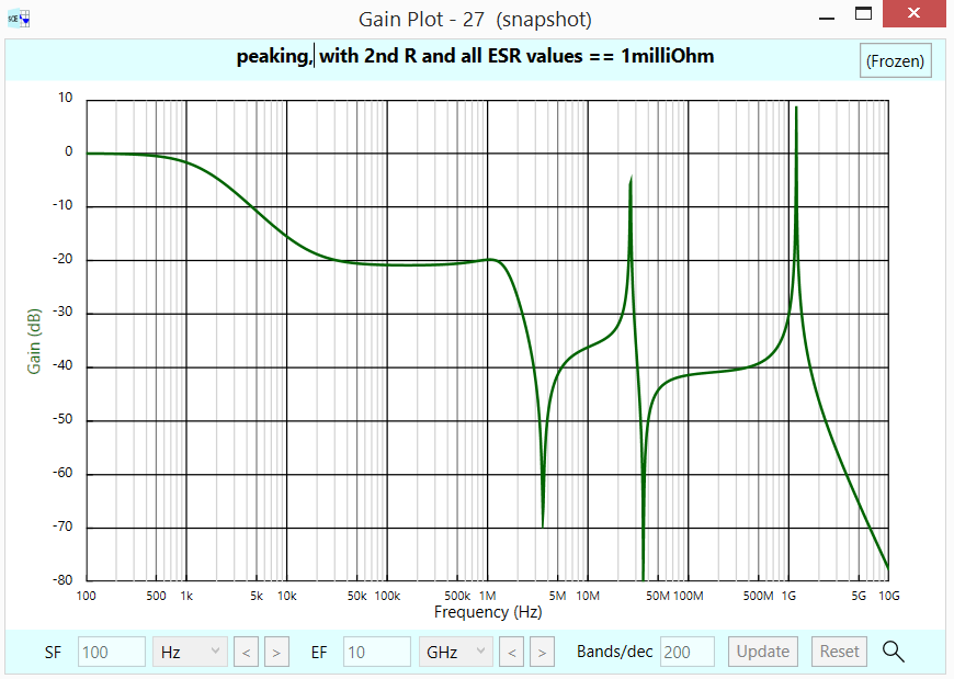
Here is the horrid peaking, if the 2nd series R is only 0.001 ohm, and ESR of all caps is only 0.001 ohm. Notice the flattop of 25MHz peak? the sim needed 2000 points per decade; at 2000 points, the 25Mhz peak rises to +3dB.

Thus we see the ESR of 0.001 ohm is not adequate. Pick lossy caps. [ the plots are "power", then "showfilterresponse" of SignalChainExplorer, free from robustcircuitdesign.com ]

enter image description here

\$\endgroup\$
0
\$\begingroup\$

The idea behind this is that smaller inductance of the 0402 packages compared to those above shifts the self-resonant frequency of otherwise equal value capacitors upwards, meaning you can get away with using larger values while maintaining the benefit of the smaller valued ones. Quite nice to have, but i'm not sure this will work for many decades of capacitor value increase (higher values still decrease the self-resonant frequency point). I think the intention here was not to populate the entire board with capacitors the size of bulk decoupling capacitors, but more conservatively going from perhaps 100nF to 470nF or even a bit higher. Keep in mind my point here is a bit subjective. I am sure however that it is possible to find the numbers and see where things stop looking 'nice' as the capacitor value is scaled up, but keep this in mind when you select your values.

Also keep in mind that the larger capacitances in smaller packages do come at a cost, economically speaking. Also too high capacitance can affect some switchers powering the node so there are other practical considerations.

\$\endgroup\$
0
\$\begingroup\$

pecifically I was thinking about this one: http://datasheet.octopart.com/CL05A105KP5NNNC-Samsung-datasheet-26589000.pdf

It's 1uF, 10V and 0402, it also works up to 85 degrees celsius and is made by a brand I've heard of. It's also pretty cheap at 0.5 cents each.

The main limitation of that one is the temperature limit. As you say it's rated to 85 C.

At 100 nF (and maybe slightly higher nowadays) you could get an X7R type capacitor that would be rated up to 125 C.

Depending on your application, that might be a distinction without a difference, or it might be the difference between success and failure.

For quite some time, maybe from about 2000 to 2005, 100 nF was essentially the highest value you could get in 0402 package with a decent dielectric, so you'll see many recommendations for that value. In the past decade, new dielectrics have been developed that allow higher values with decent WV and thermal characteristics, so it may very well make sense to use higher values, depending on your application and the environment your product will be used in.

\$\endgroup\$

Your Answer

By clicking “Post Your Answer”, you agree to our terms of service and acknowledge you have read our privacy policy.

Not the answer you're looking for? Browse other questions tagged or ask your own question.