5
\$\begingroup\$

I have a signal which I want to calculate its effective value. The signal is a voltage value read on a 33.3m\$ \Omega \$ resistor connected series to a 220V AC power line. My aim is to calculate the reactive power transferred on the power line.
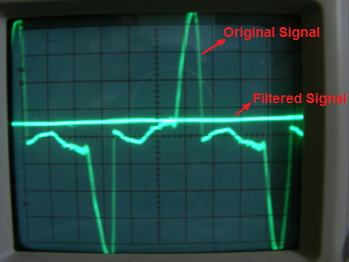
Oscillator Screen Shot
(Frequency is 50Hz. Vertical scaling is 10 mV/square for both signals.)

I obtained the "Filtered Signal" by the circuit below: Rectifier & Filter
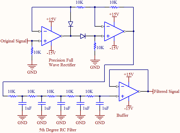
The filtered signal can be assumed to be a DC voltage level. Its value read from the oscillator screen represents 150mA current level through the current sensing resistor. This is the average value of the current flowing on the power line, isn't it so? However, I need the effective value of the current in order to calculate the power. Since the current on the line is not sinusoidal, I cannot calculate the effective value from those simple AC voltage wave formulas.

So, what can I do? I'm stuck at this point. Is there any way of calculating the effective value of this current from these available data, or any way of calculating the power directly?

\$\endgroup\$
2
  • 1
    \$\begingroup\$ Wikipedia says "effective value" is the same as root-mean-square value, but I've never heard the term used that way before. Is the RMS value what you want? \$\endgroup\$
    – The Photon
    Commented May 2, 2012 at 21:45
  • 1
    \$\begingroup\$ @ThePhoton Yes, what I want is exactly the RMS value of the signal. \$\endgroup\$ Commented May 2, 2012 at 21:51

3 Answers 3

8
\$\begingroup\$

This is the average value of the current flowing on the power line, isn't it so? However, I need the effective value of the current in order to calculate the power.

Be careful. If the shapes of the currents or voltages are not sinusoidal, knowing the RMS values for them, and the phase difference between them, is not enough. For arbitrary waveforms (as in your figure) for either one of the two (voltage or current), the only way to have an accurate calculation of the power is by integrating the product of the instantaneous voltage and the instantaneous current.

\$P=\dfrac{1}{T}\int v(t)i(t)dt \$

Nowadays, that is usually done in the digital domain. You have two ADCs (or a single ADC with two S/H front-ends). One converts v(t) and the other one converts i(t). In the digital domain, you multiply those two signals, and do the integral.

You can also do it in an analog way, using an analog multiplier and a low pass filter, but analog multipliers are tricky to use.

In summary: the circuit that you posted, that filters the shape of the current, is not valid for computing power, if the current may have the shape that you show in the figure.

\$\endgroup\$
4
\$\begingroup\$

"You can't get there from here" :-) - ie there is no practical (or known, in the general case)) way to get what you want using the heavily filtered average current value that you have.

For signals which depart more than a little from pure sine waves you need to take account of the waveform.

For reactive loads you also need to know the time relationships of the voltage and current waveforms.

For the waveform shown, which is immensely non sinusoidal, the result obtained from using the average current value will be unrelated (except by chance) to the actual value.

Your RC filter with 5 sets of 10k and 1 uF will filter well enough but it is not a formal 5 stage filter in any usual sense. A properly designed filter using one or two opamp sections will have a vastly superior performance as a low pass filter.

\$\endgroup\$
3
\$\begingroup\$

I'm guessing by "effective value" you really mean RMS. Please be more specific next time.

No, you can't determine the RMS value from the average. Sorry, but the math just doesn't work out like that. For example, the average of a sine is zero, but its RMS is it's peak divided by the square root of 2. Even something as simple as a 0-5 V square wave doesn't work. The average is 2.5 V but the RMS is 3.54 V. I just doesn't work that way.

\$\endgroup\$
2
  • \$\begingroup\$ It is actually "the average value of the full-wave rectified signal", I was shortly calling it "average value". To make the things clear, I also added the circuit schematics. \$\endgroup\$ Commented May 2, 2012 at 21:59
  • \$\begingroup\$ @hkBattousai: Even the average of the full wave rectified signal doesn't give you RMS unless you know what the wave shape is. For any given waveshape, you can compute the ratio of RMS to average, but that ratio changes with the waveshape. \$\endgroup\$ Commented May 2, 2012 at 23:06

Your Answer

By clicking “Post Your Answer”, you agree to our terms of service and acknowledge you have read our privacy policy.

Not the answer you're looking for? Browse other questions tagged or ask your own question.