2
\$\begingroup\$

When introducing the two-port network models for linear circuits, the texts start with an argument similar to this:

"To characterize a two-port network requires that we relate the terminal quantities V1, V2, I1, and I2, out of which two are independent."

enter image description here

It seems like someone in history had the idea of relating input voltage to input current and output voltage ect. and made a circuit model for his equations.

They relate V1 as a function of I1 and V2.

And I2 as a function of I1 and V2.

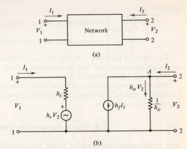
And these mathematical equations are modelled as the following circuits:

enter image description here

My question is about the motivation of the idea of writing those two equations at the beginning.

So here we have a network(as in the top figure a) and name the input voltage V1, input current I1; similarly the output voltage V2, and the output current I2.

Question:

The first equation relates V1 to I1 and V2. I have a problem here. I can make sense that the input voltage V1 has a relation to the input current I1. I can also make sense that there is a ratio between the input voltage V1 and the output voltage V2.

But when I think of some one writing the following:

V1 = hi×I1 + hr×V2

my mind gets locked.

Why two independent relations are added to equate V1?

So in a linear system, where does the idea of adding two relations come from? Is there a way to demonstrate it in an easy way?

Edit:

Here is the superposition principle:

enter image description here

enter image description here

But this principle is turning off "voltage sources". But in the equation:

V1 = hi×I1 + hr×V2

is V2 a voltage source(another input) or an output? If it is an output can we still treat it as a voltage source and employ the superposition principle?

\$\endgroup\$
4
  • \$\begingroup\$ That's a horrible expression of the superposition principle. Linear circuits can also contain current sources, linear capacitors, linear inductors, and linear controlled sources (CCCS, CCVS, VCCS, or VCVS). Also, not all resistors are linear, and a circuit containing a nonlinear resistor is not a linear circuit. \$\endgroup\$
    – The Photon
    Commented May 12, 2017 at 18:16
  • \$\begingroup\$ I see, I added a better definition now. But my question here regarding my figures, should V2 be an independent source or can it be an output to employ superposition? I mean in that two port network model is V2 a source or output? Because according to the theorem to zero V2 it must be a source isnt it? But on the other hand it looks like an input output network.. \$\endgroup\$
    – floppy380
    Commented May 12, 2017 at 18:25
  • \$\begingroup\$ It could be an independent source, but doesn't have to be. The 2-port doesn't know whether the voltage across its terminals is caused by an independent source or something else. If it is something other than an independent source, then of course \$I_2\$ will probably affect the voltage it produces, leading to more interconnected equations needing to be solved to get a complete solution for your system. \$\endgroup\$
    – The Photon
    Commented May 12, 2017 at 18:28
  • \$\begingroup\$ So in case if V2 is output(not an actual independent source), so we can treat it as a voltage source right? And zero it to find one of the relation V1 = hi×I1 (when V2=0). \$\endgroup\$
    – floppy380
    Commented May 12, 2017 at 18:54

2 Answers 2

3
\$\begingroup\$

I don't know the history, but Wikipedia dates some of the conepts to work by Lorentz(1853-1928).

The key is this:

To characterize a two-port network requires that we relate the terminal quantities V1, V2, I1, and I2, out of which two are independent.

You can pick any two of those variables as independent and then the other two as dependent variables. Because the network is linear, once you know the relationship between one set of independent and dependent variables, you can do matrix transformations to find the relationship between some other choice of variables.

Depending which you pick, there's a different name for the matrix that relates them.

If you pick \$I_1\$ and \$I_2\$ as independent, then you get the "Z", or impedance, matrix and the equation $${\bf V}={\bf Z I},$$ shorthand for $$V_1 = Z_{11}I_1 + Z_{12}I_2$$ $$V_2 = Z_{21}I_1 + Z_{22}I_2$$

If you pick \$V_1\$ and \$V_2\$ as independent, then you get the "Y" or admittance matrix, and the equation $${\bf I}={\bf Y V}.$$

Note that if we premultiply the two sides of this equation with the inverse of \$\bf Y\$ we have $${\bf Y}^{-1}{\bf I}={\bf V},$$ which tells us that \${\bf Y}^{-1}\$ is just another name for \$\bf Z\$.

If you pick one current and one voltage as independent then that's considered a "hybrid" representation and the matrix is named "\$\bf H\$".

You can even pick linear combinations of the I and V variables as the independent and dependent variables and get things like the S-matrix ("scattering matrix") and S-parameters used in RF work.

Usually we pick a representation that makes our circuit easy to understand. Or we might initially analyzer a problem using a representation that makes it easy to understand the function of some subnetwork, and then use well-known transformations between the different matrices to get a form that's easier to solve, or easier to evaluate how it will combine with other subnetworks in the full network.

For example, we often represent a common-emitter BJT circuit using the H matrix because we know the collector current is very nearly proportional to the base current, but that it varies slightly due to the collector voltage (this is exactly the circuit given in your example, and why the BJT current gain \$\beta\$ is sometimes called \$h_{fe}\$).

Edit

I guess you are trying to focus on this part of your question?

But when I think of some one writing the following:

V1 = hi×I1 + hr×V2

my mind gets locked.

You can see it in the circuit model (b) that you posted. The output current is the sum of the current through two parallel branches. One is a CCCS with gain \$h_f\$, so the current through that branch is \$h_f I_1\$. The other is a conductor with conductance \$h_o\$, so the current through that branch is \$h_o V_2\$. By KCL, the total current into port two (\$I_2\$) is therefore $$I_2 = h_f I_1 + h_o V_2.$$ Like Neil points out in the comments, this means that \$h_f\$ must be a unitless quantity and \$h_o\$ must have units of conductance.

Edit 2

You found this definition of the superposition principle:

enter image description here

This is simply wrong, or at least it's a very incomplete version of the superposition principle.

First, not all resistors are linear, and a circuit containing a nonlinear resistor can't be solved by superposition.

Second, other elements than those specified can be included in a linear circuit, such as current sources, linear capacitors and inductors, and linear controlled sources (VCVS, VCCS, CCVS, or CCCS).

Probably this definition was put in a book at a point where voltage sources and linear resistors were the only components that had been introduced. Later, the author should have given a more complete version to allow for other component types.

\$\endgroup\$
11
  • \$\begingroup\$ See also: Wikipedia's article, Two-port network. \$\endgroup\$
    – The Photon
    Commented May 12, 2017 at 16:17
  • \$\begingroup\$ Most part of your answer is not about my question. Im asking why we have the right to add two independent relations in a linear system? And your answer is "it is because the system is linear". Kind of circular to me. Or I didnt get your point. Maybe I should ask this to math guys. \$\endgroup\$
    – floppy380
    Commented May 12, 2017 at 16:22
  • \$\begingroup\$ I decided not to attempt this, too much work, but I think the OP's question was more about why can the two contributions to V1 be simply added together. I suspect he doesn't get superposition in linear systems, see last few sentences. It's not so much that's how matrices work, but that we use matrices because that's how the world works. \$\endgroup\$
    – Neil_UK
    Commented May 12, 2017 at 16:22
  • \$\begingroup\$ @Neil_UK Yes thats what exactly Im asking and dont understand why. \$\endgroup\$
    – floppy380
    Commented May 12, 2017 at 16:28
  • \$\begingroup\$ @Neil_UK In superposition we add signal contributions inputs independently and add outputs at the end ect. But in this case here they add relations/equations. One is just a ratio the other is impedance. Big confusion to me. \$\endgroup\$
    – floppy380
    Commented May 12, 2017 at 16:32
0
\$\begingroup\$

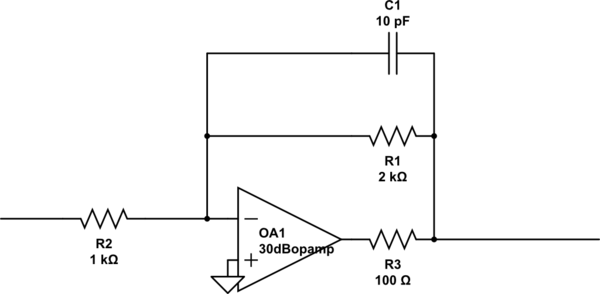
What does the input-forward-reverse-output matrix tell us, about this circuit. Since the OpAmp has 100 Ohms Rout, and only 30dB openloop gain, the OpAmp only poorly controls Vout. We have all sorts of interactions between input Rsource and output Rload. The matrices capture the entire group of interactions. Thus we can write the (4) equations, or use the matrix.

schematic

simulate this circuit – Schematic created using CircuitLab

\$\endgroup\$

Your Answer

By clicking “Post Your Answer”, you agree to our terms of service and acknowledge you have read our privacy policy.

Not the answer you're looking for? Browse other questions tagged or ask your own question.