1
\$\begingroup\$

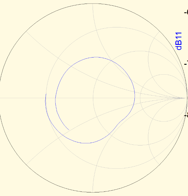
I am trying to match a dipole antenna to a 50Ω source. Problem is that for my frequencies (VHF) the complex impedance basically circles the 50Ω point between VSWR 2 and 3 lines. Because of that matching with a transformer or a lumped component seems impossible. To get around it I decided to use some relays to switch in different capacitors and inductors to get a good match for every frequency with some switching.

Smith chart of the antenna

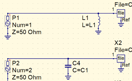
Now I'm trying to optimise these components with QUCS. I started with four sources with four different matching components. All of them go to separate sinks with the same file name.

Different matching paths for different frequencies.

I am running default Optimization block to try to optimise these four matching components. The problem is describing the goal for the optimiser. I can't give a formula like "max(S11)", because that would optimise one component to be good at every frequency. But I don't know how to tell QUCS that the goal is to minimise "max(min(S11, S22, S33, S44))". I am able to describe the algorithm in code, but don't know how to write it down in QUCS equations.

\$\endgroup\$
3
  • \$\begingroup\$ I don't know if many folk use the tool you mention but, if you are after a solution irrespective of the tool then start quoting impedances that need matching. \$\endgroup\$
    – Andy aka
    Commented Sep 8, 2017 at 14:52
  • \$\begingroup\$ I would like to do the final matching part myself, but am open to suggestions of other tools to use. I have tried several and QUCS seems to be with the best ease of use vs features. \$\endgroup\$
    – Jaanus
    Commented Sep 8, 2017 at 16:08
  • \$\begingroup\$ Try matching it to 73 Ohms instead. \$\endgroup\$
    – D.A.S.
    Commented Aug 8, 2018 at 2:24

1 Answer 1

1
\$\begingroup\$

Well, Qucs comes with a number of examples (File->Examples). One of them (filter_optimization.sch) shows how to set the optimization block... Please make sure that ASCO is installed (http://asco.sourceforge.net/)

IMHO, depending on the application you'll need to choose a lowpass or highpass LC matching network and then you'll need more or less LC stages depending on the bandwidth and the "jump" between the load impedance and Z0.

Hope it helps

\$\endgroup\$

Your Answer

By clicking “Post Your Answer”, you agree to our terms of service and acknowledge you have read our privacy policy.

Not the answer you're looking for? Browse other questions tagged or ask your own question.