In surge protection, coordination is a serious and challenging problem. In all but the simplest surge protection circuit, one has to use multiple types of components at the same time. However, some components are faster or more sensitive, other components can be slower or less insensitive. Thus, a multi-stage circuit works properly only when design engineers ensure all components parameters are carefully "tuned" to produce the correct timing, so they would work cooperatively together during a surge.
Depending on the "school of thought", standards, applications, or just parameter tunings, each surge protector can behave differently. When multiple surge protectors of unknown designs are chained together, the correct coordination is thus no longer guaranteed.
Single-Stage Protection Circuit
Let's first consider a cheap single-stage surge protection circuit, with a shunt element connected in parallel with the power lines.
How it works
A single-stage shunt protector is a crowbar circuit.
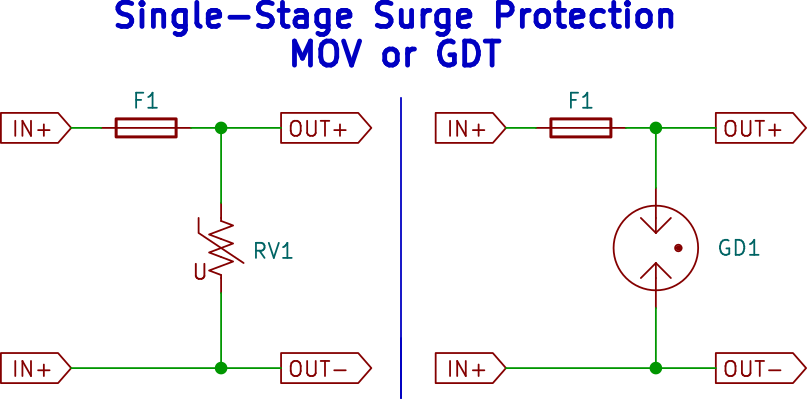
During normal operation, the line voltage is well below the threshold voltage of the shunt protector, so it behaves like an open circuit. When a surge occurs, the line voltage rises above the threshold voltage of the protective component, the impedance of the protective device decreases and creates a high current flow to ground. Since the source has a finite output impedance, the line voltage is reduced. The appliance only sees a momentary voltage droop and continues to operate.
If long-term overvoltage is a risk, such as when a signal line is accidentally connected to a power line (known as power line crosses incidents), one can also include an extra fuse F1. When the surge protector remains a short circuit for a long time, fuse F1 is eventually blown to permanently disconnect the load.
The most common component for power line protection is a Metal-Oxide Varistor (MOV), which is used in almost all surge-protected AC mains power strips and other general-purpose applications. Gas Discharge Tube (GDT) are also common for low
voltage signal or DC power lines protection due to its high current rating and low parasitic capacitance. Other protective devices include spark gaps, Transient Voltage Suppression (TVS) diodes, Zener diodes, and Thyristor Surge Suppressor (TSS).
Note that GDTs are usually not used directly across AC mains due to its hysteresis (negative resistance), which means it turns off only after the line voltage has reduced to a much lower level than the surge voltage that initially triggered it, and likely creates a long-term short circuit on the AC lines.
Performance Limitations
A single-stage circuit has its limits.
During a surge, the protector must withstand massive energy dissipation due to \$ I^2R \$ heating without being destroyed. Since GDTs use an electric arc as its conductor, the very-low resistance enables their high current ratings. On the other hand, MOVs have reasonable but lower current ratings than GDTs.
Another requirement for protectors is a fast responding time. They must react to overvoltage as soon as possible to catch transient surges. MOVs are great choices: they're diode-like semiconductor devices, so they can respond on the scale of 1 nanosecond. GDTs are not-so-great: gas ionizing is a slow process and takes time on the scale of 1 microsecond.
Bad Two-Stage Protection Circuit
To increase the protector's current rating, it calls for a two-stage protection circuit. But as we'll see, here's where all the coordination troubles start, with numerous pitfalls.
MOV protector and GDT protector in series
Let's consider what happens when a naive user (or circuit designer) connects two surge protectors from both vendors in series. One is MOV-based, another is GDT-based. If a MOV reacts fast, and a GDT withstands high current, it's the best of both worlds when we combine both, right? What can possibly go wrong?
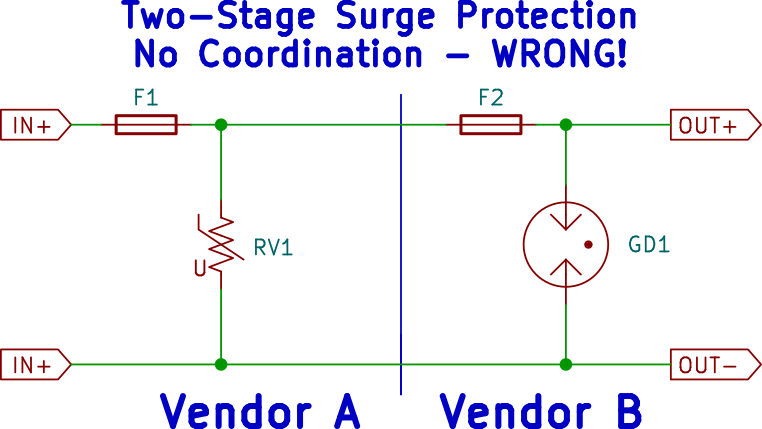
The problem is the "race condition" between the GDT and the MOV. Since GDT takes ~1 microsecond to respond, while a MOV only needs ~1 nanosecond. The MOV always wins the race as a result. During a surge, MOV immediately turns on after several nanoseconds to clamp the surge, so the GDT never sees it and never turns on!
In the best-case scenario, the GDT protector is rendered useless by the MOV protector, but the MOV protector itself absorbs the surge, so it's a only waste of money to purchase the GDT. In the worst-case scenario, the MOV is destroyed by the surge soon after it turns on and fails as an open circuit, sending the full surge voltage to the next stage and destroys the load. Only 1 microsecond later, the GDT protector finally turns on. The result is both a destroyed load, and a waste of money to purchase the MOV.
Two MOVs in parallel
Another way to increase the surge current rating is connecting multiple MOVs in parallel, as a result, the overall current rating of the surge protector is increased.
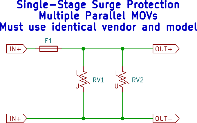
It's not as good as it seems: MOVs are not ideal resistors, equal current sharing is not guaranteed, the overall current rating will be lower than the sums of all individual MOVs's ratings. But when all MOVs are of the same types and models, the result is good enough. Thus, it's a valid and very common strategy when it's correctly designed.
However, when multiple MOV with different vendors and models are combined, current sharing is no longer guaranteed. The MOV with the lowest threshold or resistance is forced to withstand the full surge currents. The same situation occurs when multiple MOV surge protectors are connected in series.
Two-Stage Protection Done Right
Coordination via Series Impedance
The common most solution to the coordination problem is the following:
First, the large protector is placed at frontend of the circuit to do the heavy-lifting, the small protector is placed at the backend of the circuit to suppress the remaining residue surge. Both protectors are separated by a series impedance - it can be a resistor or inductor intentionally designed into a single protector. Sometimes, the parasitic inductance of the line wiring itself is assumed to provide this impedance implicitly.
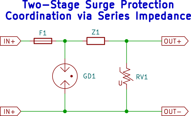
For example, the diagram above is a possible way to coordinate a GDT and a MOV. During a surge, the MOV is first turned on within nanoseconds. The large current flow creates a voltage drop across the series impedance Z1. This voltage drop creates a high voltage before Z1 even after RV1 turns on, allowing the GDT turn on after 1 microsecond as well. As a result, both components suppress the surge cooperatively, and the total current rating of the surge protector is increased.
Coordination via Semiconductor Current Limiter
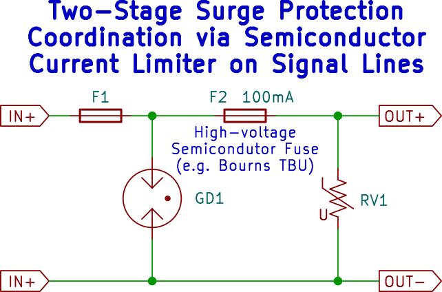
For protecting low-voltage signal lines, another attractive solution to coordination is special semiconductor current limiters. They're high-voltage low-current resettable fuses made via semiconductor switches. During a surge, the secondary protector first turns on to absorb the initial transient. Once current reaches 100 mA or so, the load is disconnected by the switch and remains fully protected as long as surge voltage does not exceed the rating of the switch. For extra safety, GDTs continue to provide primary surge protection.
Conclusion
The discussion above barely scratched the surface, there are many surge protection circuit topologies for different applications. But as we can see, mixing surge protection circuits can create the following outcomes:
If a high-threshold, high-current protector is located at the frontend of the circuit, a low-threshold, low-current protector is located at the backend of the circuit, and both are separated by a series impedance, both protectors work cooperatively when they're sized properly.
When a high-threshold and a low-threshold protector are chained together, only the low-threshold protector will likely remain functional.
Only when reasonably matched MOV protectors are chained together, their current ratings are increased.
The possibility that surge protectors interact in a way that make all of them ineffective cannot be ruled out in unusual circuit topologies, but is unlikely for popular MOV-based protectors.
These conclusions explain why small surge protectors in home appliances usually don't interfere with the operation of the large surge protectors in the electrical box. It also suggests that a whole-house protector is not always a replacement for smaller protectors at appliance's side.
It also suggests that chaining surge-protected power strips is probably a non-concern for home applications, strictly from the perspective of protection coordination (not circuit overload). Losing one protector from a chain of two usually has negligible effect. Furthermore, many appliances have internal protections inside their power supplies. When these appliances are plugged into a surge-protected outlet, there's still a chaining even if the user is not doing it willingly.
The disclaimer not to chain surge protection is mostly to avoid legal liability for two reasons. First, a chained surge protector is operating under unknown technical conditions that it's never designed or tested for - although it's probably not a big deal. Furthermore, there's an increased risk of fire if the circuit is overloaded.
For distribution-box level installation, industrial applications, and protection circuit design, the problem of protector coordination can no longer be ignored. Furthermore, it also explains why most surge protectors only use cheap and boring MOVs for protection, in contrary to the high-tech impression that vendor's marketing wants to create. Cost is one reason, the fast-response of MOVs is another, the difficulty to reliably coordinate multiple forms of protection (especially with MOVs) is likely also a major reason.


