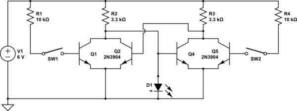
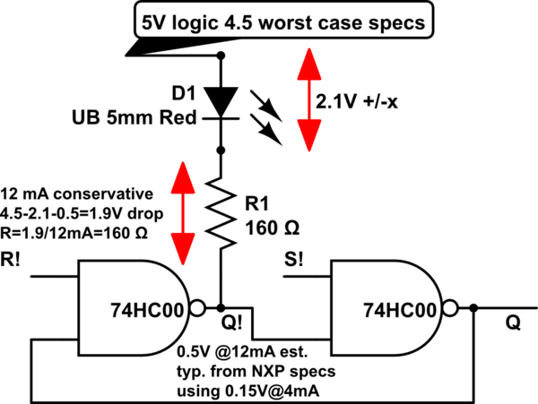
I am trying to create an SR Latch with two NOR logic gates that lights an LED. I am implementing the gates using 2 transistors and 2 resistors each.
Here is the schematic:

simulate this circuit – Schematic created using CircuitLab
The goal is for Switch 1 to be the Reset button and for Switch 2 to be the Set button. My concern is if there will be enough current to light up the LED (I am hoping to get 5mA-20mA flowing through it).
I am confused on how to find the resistance and current because different paths split into multiple other parallel paths. (i. e. the path that \$R_2\$ is on splits into two, and one of those paths splits into two more)
I know that \$\frac{1}{R} = \frac{1}{R_1} + \frac{1}{R_2} + ...\$ and that \$I = V(\frac{1}{R_1} + \frac{1}{R_2} + ...)\$ But how do I apply this to the different paths of the circuit?
I would like to know how to find how much current is flowing through a component and how much resistance is on a path in schematics similar to this one (meaning they use logic gates implemented similarly).

