21
\$\begingroup\$

I am getting a PCB manufactured for a project that I am working on. One of the parts, the A4950 motor driver (datasheet), has a "pad" on the bottom, which is meant to be soldered to GND of the PCB for thermal dissipation. I am only ordering a small quantity of the PCBs, so it would not make sense for me to buy some sort of PCB assembly service. I am planning on soldering the components myself.

I was thinking about the soldering, and I am unsure how I would go about (using a soldering iron), soldering the pad on the bottom. Is this even possible to do by hand?

I was thinking maybe I could manually apply some soldering paste to the PCB, but I'm not sure whether that is an appropriate use of solder paste or not.

How can I prototype an IC with an exposed pad on the bottom?

\$\endgroup\$
8
  • 4
    \$\begingroup\$ That's the kind of question you ask (and answer) before you design the board or order the parts. Parts with a solder tab underneath can't really be soldered by hand with an iron. You need a reflow oven. I can't help you with that. I avoid those kinds of parts - I only do hobby stuff, and have no desire to get into doing reflow in a home environment with some kind of lashed up rig made up of a toaster oven, patience, and luck. \$\endgroup\$
    – JRE
    Commented Jan 6, 2018 at 21:30
  • 4
    \$\begingroup\$ @JRE I haven't yet sent it off to be made. i was waiting to get an answer here first ;) \$\endgroup\$
    – eeze
    Commented Jan 6, 2018 at 21:40
  • 3
    \$\begingroup\$ It can be done by hand using hot air, but your first few efforts may not be successful. If you are able to apply solder paste neatly to the pad, that will improve chances of success, I think. \$\endgroup\$
    – user57037
    Commented Jan 6, 2018 at 21:52
  • 3
    \$\begingroup\$ The tool you want for this is not a "paint removal" "heatgun" but rather a hot air rework tool. The latter are quite inexpensive now, and extremely useful, not only for installing parts like this, but also for removing any multi-leaded component. If you must use a painter's heat gun, you should probably install this chip first, before any other chips and definitely before any cheap plastic connectors. \$\endgroup\$ Commented Jan 6, 2018 at 22:40
  • 2
    \$\begingroup\$ Another trick, far inferior but sometimes workable, is that if you are designing the PCB you can put some large vias through the pad, granting access for heat and wire solder feed from the reverse side. Or if the part only has leads on two sides, you may be able to extend the pad contact beyond the package and heat it that way. But really consider it an excuse to get the hot air tool - it will get you out of so many difficulties. \$\endgroup\$ Commented Jan 8, 2018 at 2:07

10 Answers 10

22
\$\begingroup\$

The absolute best way to do this is to preheat everything with a large high flow hot air source or oven. Apply paste first, if you have it, or a little bit of wire solder to the pad. Then pre-heat. The pre-heat temperature is around 125C or so.

Once everything is heat soaked at 125C, apply localized hot air directly to the part to be soldered and immediately around it. The temperature should be hot enough to melt the solder, but not overheat the part. A lot of cheap hot-air equipment has poor temperature setting and indication. So you may need to experiment. If the solder melts extremely fast, it is too hot. If it melts in about 10-45 seconds, that is probably good. If it takes a full minute, then it should probably be hotter. Often, you will notice the part kind of self-aligns itself and snaps into place when the solder is all melted. This is a good indication that it is hot enough.

Small parts will probably reflow much faster than large parts, and may not need as high a temperature either. Your first efforts may not work well. So keep track of the time, temperature and results. Once you find a winning recipe, stick to it.

If you don't have any way to pre-heat the whole board, then you can just do it the way Arsenal says. If you are repairing a board that went through a reflow oven, keep track of time and temperature when you remove the part. This will give you a good idea of time and temperature required to install the new one.

For large parts, I sometimes don't place them prior to heating. I hold the part with tweezers near the edge of the hot air stream. I use hot air on the pad until I can see that the solder is thoroughly melted, then I place the hot part on the molten solder pad with tweezers. Don't place a cold part on hot solder. The part has to be hot, too, otherwise you will get a cold solder joint. If you do it this way, you can stop heating almost immediately after you place the part. Oh, also, use flux.

\$\endgroup\$
7
  • \$\begingroup\$ this might need to be a seperate question, but do you think that if i didnt solder the pad, but put a small heatsink on top, do you think that might work? \$\endgroup\$
    – eeze
    Commented Jan 6, 2018 at 22:09
  • \$\begingroup\$ That is very hard to say. However, being able to solder parts like that is a useful skill. Just look at the money spent on extra parts as an investment in your skillset and training. If you do it 5 times, I believe you will become pretty good at it. Use flux, get magnifying glass or microscope if needed, have someone help you if you need a third hand, etc. Watch some videos on youtube. \$\endgroup\$
    – user57037
    Commented Jan 6, 2018 at 22:17
  • 1
    \$\begingroup\$ Maybe worth pointing out that it will usually be very obvious when the part has gotten enough heat as it will self-align to the footprint. It should be pretty straightforward with a 2-layer board, but I think a multilayer board with internal planes might be worth borrowing time on a reflow oven for. \$\endgroup\$ Commented Jan 6, 2018 at 22:26
  • 1
    \$\begingroup\$ Heating at 350C or more will result in melting the part and the PCB. Never use more than 250C. \$\endgroup\$
    – Fredled
    Commented Jan 6, 2018 at 23:05
  • 2
    \$\begingroup\$ I think it's just the surrounding air which gets mixed into the stream cooling it off rather quickly. \$\endgroup\$
    – Arsenal
    Commented Jan 8, 2018 at 13:24
15
\$\begingroup\$

One cheap and easy way to do this is to drill a small (50 to 100 mils) hole in the center of the pad on the PCB. Solder the pad itself but not so much it puddles. Solder or at least flux the pad on the IC and solder just the corner pins to the PCB.

Put a 60 watt or so solder iron with a small chisel tip into the back of the PCB and into the hole you drilled. This will heat the IC pad and the PCB pad enough to fuse together. Use a gloved finger to press the IC flat as it fuses to the pad. STOP the instant this takes place. Now you can manually solder or use infra-red or a heat gun to solder the remaining pins.

This works well once you have done it a few times. You do loose some heat transfer to the PCB using this trick, but less chance of damage from cooking the IC or PCB if other procedures last too long.

EDIT: The only time this trick will not work is with multi-layer boards and you know there are traces you might cut through. However IC's that have a bottom pad for grounding and/or heat sink normally have no hidden traces under them. At most there would be a grounding pad with a ring of SMD capacitors around its perimeter. Unless it is very small it is still safe to drill a small hole in the center.

Thanks to @MichaelKaras for his suggestion that if you are doing your own board layout, a 50 mil hole can be embedded in the board that is plated through at the board house. This creates more surface to transfer heat and avoid drilling burrs in the copper if it is done later on. The plate through also allows more heat to be picked up from the solder iron so this step happens fast. Also it allows you to route a few traces around the hole if it simplifies routing.

\$\endgroup\$
3
  • 3
    \$\begingroup\$ Love this. Sometimes you have to get creative to get the job done. \$\endgroup\$
    – user57037
    Commented Jan 7, 2018 at 20:56
  • 4
    \$\begingroup\$ I've used a scheme very similar to this in the past with success. Instead of drilling the hole after the fact I designed the thermal pad with a solder tip sized hole right into the footprint definition. Doing this prevented inner layer routing from going through where this hole was located. I chose to use a plated hole. \$\endgroup\$ Commented Jan 8, 2018 at 3:37
  • \$\begingroup\$ @MichaelKaras. Smart idea. Gives you better heat transfer. \$\endgroup\$
    – user105652
    Commented Jan 8, 2018 at 3:40
5
\$\begingroup\$

Here is a way to do it without a hot air gun.

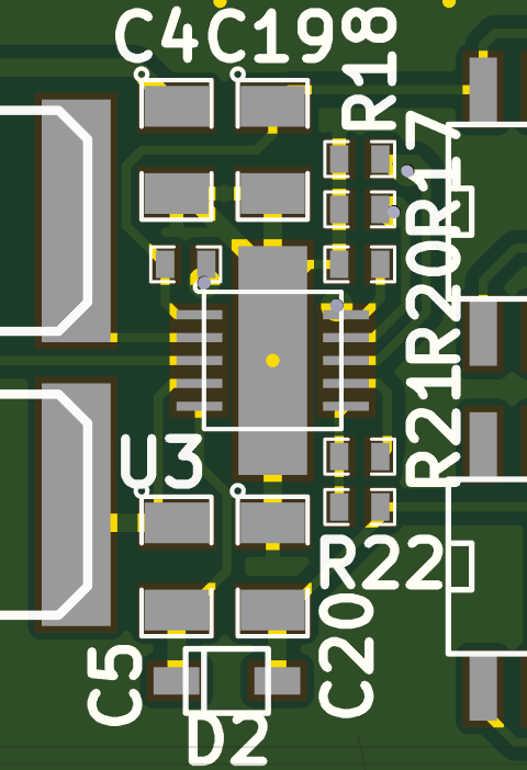
Because the part only has pins on two sides, you can make the center pad longer, like done here for U3. That way you can heat it with the chip in place:

PCB with extended pad

Then pre-tin both the pad on the device and on the pcb, and heat until it melts together. After that you can solder the rest of the pins normally.

\$\endgroup\$
1
  • 3
    \$\begingroup\$ in your example image this might work, because the pad isn't connected to a large surface area. but for something that will dissipate a lot of heat like motor driver chip, a much larger plane should be used, possibly connected using thermal vias. given the whole point of this is to conduct heat away from the chip, it becomes very difficult to actually heat up the pad unless you have a way of heating up the rest of the board as well \$\endgroup\$
    – user371366
    Commented Jan 7, 2018 at 19:22
3
\$\begingroup\$

If you have soldering paste and an adjustable (air flow and heat) hot air gun available, you can use those.

What I use to do is put soldering paste on pads (I use a syringe with a very fine needle to apply it, it really doesn't need much), place the component as best as possible. It doesn't have to be 100 % perfect, especially if the board has solder resist, as the reflowing soldering paste will allow the part to align itself a bit, but not too much.

Then I use low air flow (the part could be blown away) with around 350 to 400 °C and try to evenly heat around the part. At some point the solder paste will start to reflow at the pins. To get the bottom pad, it needs a bit more heat, so I keep going for a few more seconds around the chip.

If there are small parts (decoupling capacitors for example) in close proximity to the chip, be ready for them to fly away or tombstone on you.

So after you are done, inspect the board closely for any shorts which might occur during this procedure - it is not uncommon for me at least.

This method puts thermal stress on the PCB, so after around 4 or 5 attempts the PCB will show signs of degradation and I usually use a new one.

\$\endgroup\$
5
  • \$\begingroup\$ there will be decoupling caps nearby, but when you said "be ready for them to fly away or tombstone on you" you meant that would only happen if they were already soldered when i use the heatgun, right? \$\endgroup\$
    – eeze
    Commented Jan 6, 2018 at 22:04
  • \$\begingroup\$ this might need to be a seperate question, but do you think that if i didnt solder the pad, but put a small heatsink on top, do you think that might work? \$\endgroup\$
    – eeze
    Commented Jan 6, 2018 at 22:09
  • \$\begingroup\$ @eeze yes, only when the components are already in place it will be an issue. Your heatsink on top might work out, but that is hard to answer - depends on your application as well, if the part is not active a lot of the time or isn't loaded with the full current, you might even get away without any heatsinking. And on some parts the ground connection is essential for operation because it actually provides more than just a heatsink. \$\endgroup\$
    – Arsenal
    Commented Jan 6, 2018 at 22:34
  • \$\begingroup\$ Heating at 350C or more will result in melting the part and the PCB. Never use more than 250C. Do you realy heat at these temperatures? \$\endgroup\$
    – Fredled
    Commented Jan 6, 2018 at 23:02
  • 1
    \$\begingroup\$ They do not melt and I never managed to fry a part using this method. The PCB does degrade a bit, but if you manage to get it right on the first run, it's fine. You shouldn't use these temperatures with a connector - those plastics will melt, but ICs never melted on me yet. \$\endgroup\$
    – Arsenal
    Commented Jan 6, 2018 at 23:30
3
\$\begingroup\$

[disclaimer: This technique is proposed only for one-off prototypes.]

One time, I had to solder an SOIC chip with a thermal pad to a 2 layer board. I didn't have to use solder paste. Here's how I did it.

  1. PCB layout. The bottom layer of my the PCB served as a ground plane. I've added vias under the IC, which connected the thermal pad to the bottom layer ground plane. The main purpose of the vias was to conduct away the heat dissipated by the IC. The same vias can conduct the heat needed for soldering.

  2. Solder the accessible gull wing leads on the outside of the IC. This will hold it in place.

  3. Optional, but very helpful. Apply "bulk heat" to your PCB. You can use an a oven. Even a household hair dryer might work for this. [I use an industrial heat gun, which is an overgrown a hair dryer.] The purpose of bulk heat is to reduce the amount of "topical heat" which you will apply with a soldering iron in the next step.

  4. Precision heat. Turn the board over. Stick the soldering iron at the the via opening on the bottom side. Feed the solder and flux into the vias generously. The solder will flow through the vias to the thermal pad, where it will make electric and thermal contact.

---

1I've used the old-fashioned leaded solder for step 5. It has the lower melting point than the modern stuff.
2If you have a choice of tips, use a medium or large tip for step 5.
3If your board has got inner plane layers, it will be harder to make this method work.

\$\endgroup\$
2
\$\begingroup\$

Hot air gun and lots of flux. Another method that I have used to solder these parts with a soldering iron is put a few vias on the thermal pad and solder it through that. It's not the best method but it good enough for prototyping.

If the power dissipated in the part is low ( like 1/3 or 1/4 ) of the rated dissipation capacity, you might be able to not solder the pad at all (unless it's also used for grounding or an electrical connection, which for a lot of parts the thermal pad is connected to a pin and the pad).

Another option if the electrical connection is not needed with the thermal pad on the bottom is to put a heatsink on the top for prototyping (sometimes even a block of aluminum will do, anything to increase the surface area to the air).

\$\endgroup\$
1
\$\begingroup\$

To solder pads that are under the component you sadly can't use a soldering iron, you need a heat gun or better a station. ....and plenty of Flux. Hope this answers your question.

\$\endgroup\$
1
\$\begingroup\$

Hot air gun, solder paste and flux is the right answer as others posted. However I would like to add precisions to the temperature to be used. Pre-heat at around 120C for one minute, then gradualy increase heat by 10C steps every 5 sec until you reach 240C or 250C (for larger parts). Then count slowly until 5 and start decreasing temperature step by step. decreasing can be done faster. Back at 125C you can turn off the hot air. DO NOT heat at higher temperature than that! Your part and the PCB and the other parts around will melt. In the datasheet the maximum reflow soldering temperature and time should be written. Do not exceed them. If you don't have a regulated air gun and can't have one, you can try playing with a digital thermometer but it's much more difficult and less reliable. I strongly recommand buying one if you do more than 10 pieces. The air gun can also be used to weld or repair plactics, solder contact sleeeves and other things.

\$\endgroup\$
1
  • 1
    \$\begingroup\$ I would suggest pre-heating longer than 1 minute unless there is something on the board that can become damaged at that temperature. Most IC's can be stored at 120C for extended periods. \$\endgroup\$
    – user57037
    Commented Jan 7, 2018 at 2:05
1
\$\begingroup\$

A very sloppy but existing way to do it is to have the pad on the board slightly bigger, solder a short thin wire to the component itself then after placing the component, solder the remaining of the wire to the pad. This will raise the component a mm or so away from the board, you can push some heat-conductive glue under it. :) I can see the flinches on faces and I understand completely, but it can actually work, takes care of electrical connection and heat, and does not require an air gun.

\$\endgroup\$
3
  • 1
    \$\begingroup\$ I grimaced, but I kept reading to the end anyway. Worth a try in a dire situation I guess! \$\endgroup\$
    – user57037
    Commented Jan 7, 2018 at 20:58
  • 1
    \$\begingroup\$ @mkeith Heheh, exactly. Worth mentioning in case of a dire situation though. \$\endgroup\$
    – Szidor
    Commented Jan 7, 2018 at 21:19
  • 1
    \$\begingroup\$ Desperate times call for desperate measures. \$\endgroup\$
    – DKNguyen
    Commented Jun 20, 2019 at 21:36
1
\$\begingroup\$

This is possible to solder by hand if you design the bare board with a hole through the board that is large enough for the soldering iron tip to fit but you will also need to have a ground pad. Take a look at the picture for reference. I highly do not recommend doing this but if you are only building a handful of boards then this will work. If you ever decide to get the a larger volume, remove the hole and hire a CM. The image is of a dfn with a ground pad.

Use this link for image.

\$\endgroup\$
1
  • \$\begingroup\$ Also, don't underestimate how big a tip needs to get through that hole to properly heat it up. \$\endgroup\$
    – DKNguyen
    Commented Jun 20, 2019 at 21:37

Your Answer

By clicking “Post Your Answer”, you agree to our terms of service and acknowledge you have read our privacy policy.

Not the answer you're looking for? Browse other questions tagged or ask your own question.