I want to make a serial system over RF to receive messages sent from a computer, so I can understand how digital radio works on the bare metal. The one part I don't understand is how a sender and a receiver sync up the start and end of their bytes. It seems like it would be really easy to lose synchronization and end up with everything shifted by a few bits. How do two serial nodes sync up the start and end of their bytes?
-
\$\begingroup\$ It might be educational to look at clock recovery. Link: en.m.wikipedia.org/wiki/Clock_recovery \$\endgroup\$– Sam GallagherCommented Apr 30, 2018 at 12:44
-
2\$\begingroup\$ Possible duplicate of UART receiver clock speed \$\endgroup\$– Olin LathropCommented Apr 30, 2018 at 14:46
-
\$\begingroup\$ They do it with sync bits. \$\endgroup\$– Hot LicksCommented Apr 30, 2018 at 22:00
4 Answers
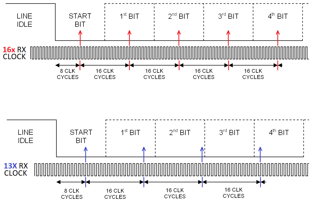
UART timing for asynchronous data relies on knowledge of the data rate and having a clock that is typically 16 x faster. The top half of the picture shows how data is re-synchronised and the bottom half shows a badly synchronised system (13x clock rate) just as an example: -
In the absense of any data edges, the correctly timed clock can sample the data pretty much at the middle of the symbol. In the lower picture, and without data edges to retime things, the 13x clock will eventually make an error.
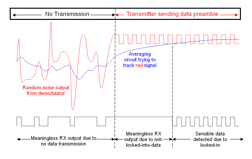
For the bigger "radio picture" you have to send a preamble to get things started i.e. you can't just hope to get lock straight away because there are many factors involved. Here's a picture I drew some time ago that explains how a preamble would work on a simple FM radio transmitter and receiver: -
And here is the previous answer that included that diagram. More useful information contained.
UARTs (rs232) have a start bit (0) and a stop bit(1). see Andys diagram. But they use wire, and the noise is very low -basically none.
On a noisy link, this works very badly. If the start bit is wrong, everything after it is wrong, and stays that way.
Radios don't generally do this, they more likely have a preamble which is has a warm up burst of 1/0's for the tx and rx to stabilise, and get bit sync, then a magic sync block, eg 32 bit unique pattern to initially sync blocks, then data blocks with error correction. Note that error corrected data blocks can be self syncing - they are only valid when sync is correct.
The codes are chosen to always have enough 1/0 transitions to keep in bit sync. ie. you can't get a run of 32 1s, there will always be a transition every N bits, worst case.
If you do use a UART over radio, the preamble should be chars that have a single 0/1 transition in them, so that the UART can get back in sync. As should be obvious, if you data was 1/0/1/0 then the uart would never know which edge was the start bit. As you can see from Andys diagram it wants to have roughly equal 1/0 balance. So 0xF0 is ideal, the sequence will be start=0 0000 1111 stop=1
In asynchronous communication you have a defined speed, the baudrate.
The receiver knows how long a bit time is. It waits for an edge and then starts counting till it is in the middle of the bit-time. Then it samples the input.
Waiting for en edge is done using 'oversampling'. You read the input status much faster then the bit rate. Common is to use 16x oversampling, but 8x also works.
There is free software that implements a UART.
If you want to see how it is done in hardware find Verilog source code. If you know C you can almost* read Verilog code.
*Apart from some very important details :-)!
Sorry missed out on the 'start and end of their bytes' part.
A UART starts with a start bit which is always low. It ends with a stop bit which is always high. Thus you wait for a 0 on the line and you know that is the start bit. You then count e.g. 10 bits (start, 8 data, stop) and the tenth bit should be high. It is very well possible that a continuous bit stream is sampled at the wrong point and still honors the 'start is low stop is high' protocol. I therefore try to have gasp between bytes to prevent this.
It might be instructive to look at a simpler algorithm for finding the stop and start bits. First, sample the input at 4 times the bit rate.
If you data rate is 9,600bits per second, then you'll want to sample it at 38,400 Hz.
When there's no transmission, you'll get a great deal of noise, and the sample input may see random highs and lows.
When a start bit is sent, you'll sense it on at least 3 consecutive samples. Thereafter, you'll sample every 4th sample as the actual bit received, offset by one sample so it's close to the middle of each bit.
You will eventually receive the stop bit - if it's not correct, then you can discard all the data and try again, waiting for a start bit.
That's the simple case. Once you have that working, you'll find you're still getting bad data, and that's where you employ more techniques to recover the data:
- Instead of using only one sample near the middle of each bit, look at all three samples that should occur inside the bit time, and use majority vote to determine the actual bit value
- Increase the sample rate to 8x or 16x, which will give you a much larger number of samples per bit to use, and get you closer to collecting information throughout the whole bit rather than just 3/4 in the middle of it.
- Store the data stream while receiving, and use a correlater that moves along the stream to find the start and stop bits. This way you're not throwing out a possible byte because you got a bad start bit right before the real data.
- Rather than sampling in the middle of the bytes, look for the transitions - RF sends transitions better than static levels. Find the beginning of the start bit, then using a small window around every bit transition, look to see if there's a transition, and then you'll have some information about the previous bit and the next bit.
However, straight up USART signals are not appropriate for RF. Consider looking into Manchester coding. Rather than sending data as highs/lows, you send it as transitions from high to low or low to high. It makes clock recovery much easier, as it encodes the clock into every bit, and it operates on transitions which is RF's natural friend. You can't send it as quickly, but it will be much more reliable.
Also consider error detection and if possible, error correction. With simple error detection you will be able to verify whether adjustments to your algorithm are improving the signal or not objectively.
-
\$\begingroup\$ Using an odd oversampling multiple works slightly better than an even one. Using 3x oversampling, for example, allows for a full +/- 1/3 of a bit time worth of slop, while using 4x only allows one to allow for either -1/2 +1/4 or -1/4 +1/2. \$\endgroup\$– supercatCommented Apr 30, 2018 at 15:25
-
\$\begingroup\$ @supercat Probably a good discussion for a follow up question. There are merits to both, however with 3 you can really only trust one sample, the other two could be very close to the transition and without additional effort you don't know which of the other two you can trust. With 4 you get two samples that are known to both be at least 1/4 bit time away from the transition. This being a simple example I didn't go further, but certainly depending on the actual noise experienced one or the other might perform better. \$\endgroup\$ Commented Apr 30, 2018 at 15:37
-
\$\begingroup\$ With 3x, you get one sample that's at least 1/3 of a bit time away from the edge. With 4x, you get two that are 1/4 away. If both samples match on every bit, that would suggest that are probably good, but if they don't match you may not know which one is "right". BTW, another approach which I'm surprised I don't see more often implemented is to use 2x oversampling but reset the timer when the start bit is received. \$\endgroup\$– supercatCommented Apr 30, 2018 at 15:52
-
1\$\begingroup\$ @supercat Yes, and we could go on. It is an interesting discussion because I'm sure there are cases where one would make more sense than the other and vice versa depending on the requirements and specific environment. I personally wouldn't use either unless required - they're both really scraping the bottom of the barrel. I used a low sample rate to illustrate the answer and make it simpler, but suggest a higher sample rate in general. \$\endgroup\$ Commented Apr 30, 2018 at 15:58


