1
\$\begingroup\$

I need to trigger remote devices through their hardware trigger inputs simultaneously (within 1 ms) from a single trigger source which has a timer output. So basically the 0/5V pulse-train at around 40Hz will trigger many devices simultaneously. The distance between the trigger source and a device is varying between 5 meters up to 200 meters. Total number of devices can be around 10.

I'm planning to use the following scheme:
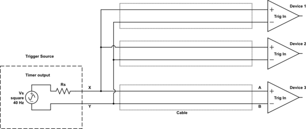
schematic

simulate this circuit – Schematic created using CircuitLab

I can add an opamp buffer just after the the trigger source that is not a problem. But I really want to minimize extra components or electronics in between unless it is ready made modules ect. in the market that I can buy.

Is there any problem to use this scheme in this case?

One of my worry is whether I need a termination resistor at the device trigger inputs, because the sharp rising edges of the pulses can be an issue for ringing?

Another worry is the false triggering due to glitches due to interference ect. RC filters needed at the device inputs? (I plan to use coaxial cables)

Or is there another robust way to implement for this scenario?

\$\endgroup\$
2
  • 1
    \$\begingroup\$ Do the remote devices have their own power supplies? Are you planning on using two coaxial cables per run for differential signals or what? \$\endgroup\$ Commented May 8, 2018 at 15:14
  • \$\begingroup\$ Yes they have their own power supplies. T was planning to send single-ended way. \$\endgroup\$
    – floppy380
    Commented May 8, 2018 at 15:29

2 Answers 2

1
\$\begingroup\$

Generally, there's a lot of clock distribution ICs from most major silicon manufacturers (TI.com, analog.com, onsemi.com, st.com, maximintegrated.com …) that serve the purpose of exactly this: distributing clocks.

However, at your distances and your frequencies, the problem really isn't what these were built for.

Note that your schematic is a bit ambiguous: when driving long lines, you'd definitely want a defined termination impedance, i.e. effectively, some resistance to sink power into.

Ideally, I'd recommend a differential line driver (for example, the ones specified for RS485) for each of the lines. There's multi-port devices that you can use to implement this.

Cost-wise, a simple multi-channel opamp with some drive strength can be used in a voltage follower + inverter way to generate your differential signaling. That would only need the opamp (and maybe a decoupling capacitor on the power supply), and termination resistances, and no further components, and would be super cheap.

With the multi-core transformers as found in every Ethernet devices (super cheap!) you could implement the same balanced (==differential) signalling with only one opamp channel per trigger, with the added advantage (or disadvantage, depends!) of allowing separation of potentials.

Generally, 1 ms is pretty doable with standard computing and wired networking hardware – a single board computer at each end (e.g. raspberry pis), and a network switch (or, hub, really), as well as one line of netcat command line could implement the same functionality, and if you need logic at every end, anyway, that'd allow you to reduce your overall complexity and potentially cost. 200m of copper twisted pair fast ethernet cabling isn't 100% legal by the standard, I think, but it usually works reliably. Generally, using full computers to do this is total overkill – I just wanted to mention this option in case it solves problems further down the line.

\$\endgroup\$
7
  • \$\begingroup\$ If I have one trigger source for each output this will be easy then. The board I have a timer and many digital IO which can work with SSR modules. I can use two boards and use upto 16 digital outputs. This is the board mccdaq.com/pdfs/manuals/SC-1608.pdf I can turn them on and off simultaneously at the same time. But is there a any ready module to convert 0/5V signal to RS485 or any other diff format? IC chips come out when I search and the company I work with do not allow me to build anything but buy. \$\endgroup\$
    – floppy380
    Commented May 8, 2018 at 15:39
  • \$\begingroup\$ yes, as said, there's a lot of RS485 transceiver ICs and modules. You put this all as a shoppiung question - and these are off-topic here :( \$\endgroup\$ Commented May 8, 2018 at 15:41
  • \$\begingroup\$ I have some time restriction to find a solution to this. I need a converter for each IO from 0-5V to diff ended. I cannot find the keyword. \$\endgroup\$
    – floppy380
    Commented May 8, 2018 at 15:42
  • \$\begingroup\$ I really don't see enough on that restriction in your question to be of any help. again, there's plenty RS485 converters if you look at the large electronic distributors, and you shouldn't be asking shopping recommendations here, but design questions. \$\endgroup\$ Commented May 8, 2018 at 15:44
  • \$\begingroup\$ okay i will delete the question then i didnt know thanks \$\endgroup\$
    – floppy380
    Commented May 8, 2018 at 15:45
0
\$\begingroup\$

For 1ms, which is not exactly a precision requirement, I would probably just use an opto coupler (maybe one of the dual diode 'AC' ones) with a series resistor at each device.

Job done?

The problem with RS485 is that it has a limited common mode range, which is FAR more restrictive then the opto isolated solution.

\$\endgroup\$
4
  • \$\begingroup\$ I have found this optocoupler module uk.rs-online.com/web/p/optocouplers/5330003 For each digital output I can install this. But I really dont understand how this will work as good as diff signalling. Can you explain a bit more how come optocoupler solves the issues l mentioned in question? Thanks \$\endgroup\$
    – floppy380
    Commented May 8, 2018 at 16:04
  • \$\begingroup\$ Do you mean optocouplers at the trigger inputs of each device or at the trigger source side? \$\endgroup\$
    – floppy380
    Commented May 8, 2018 at 16:13
  • \$\begingroup\$ Opto at the trigger input of each device, keeps them isolated from each other and from any ground voltage differences. Something like a SFH620AA with a few hundred ohms in series, but there are plenty of options. \$\endgroup\$
    – Dan Mills
    Commented May 8, 2018 at 16:57
  • \$\begingroup\$ I opened a new question regarding this here: electronics.stackexchange.com/questions/378660/… Would be great to have your feedback. \$\endgroup\$
    – floppy380
    Commented Jun 7, 2018 at 22:25

Your Answer

By clicking “Post Your Answer”, you agree to our terms of service and acknowledge you have read our privacy policy.

Not the answer you're looking for? Browse other questions tagged or ask your own question.