1
\$\begingroup\$

So I'm fairly confident in my ability to do circuit analysis on closed circuits, that is, circuits where all loops, sources, and elements are given. However I still find myself getting stuck on circuits where only a particular section of the system is given.

For example: In a problem I'm trying to solve, it is asked to use Thevenin's theorem to simplify this circuit:

enter image description here

I'm honestly quite lost, I understand that the voltages given at the terminals are relative to ground, but I have no idea how to translate those into an equivalent source. My first instinct would be to start by reducing the outside parallel resistances, which would reduce the circuit down to a T-shape with equivalent resistances of 5 ohms on each side. From there I'm stuck. Would I add the voltages as sources in series with the resistor?

Any intuition on best practice when considering systems like this would be appreciated. Thanks!

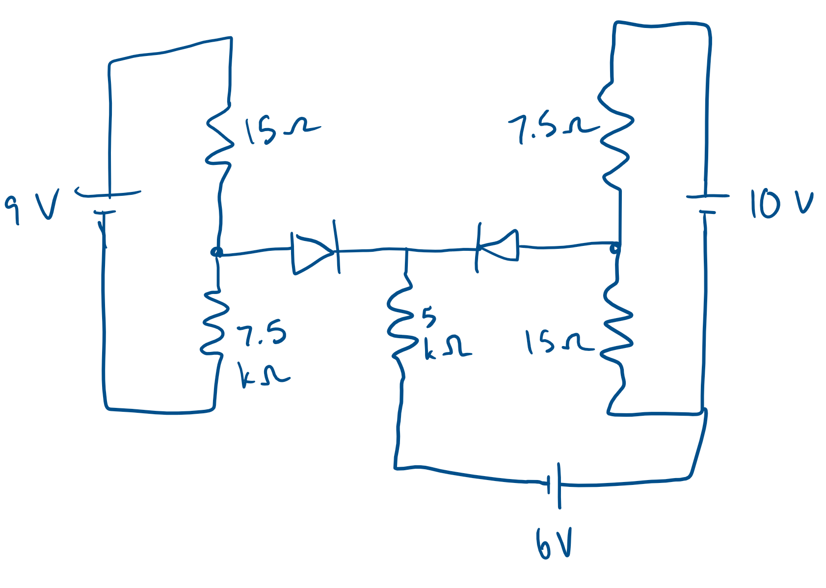
Edit: So I think I understand, flipping around some signs, would the following be an appropriate representation?

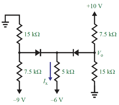
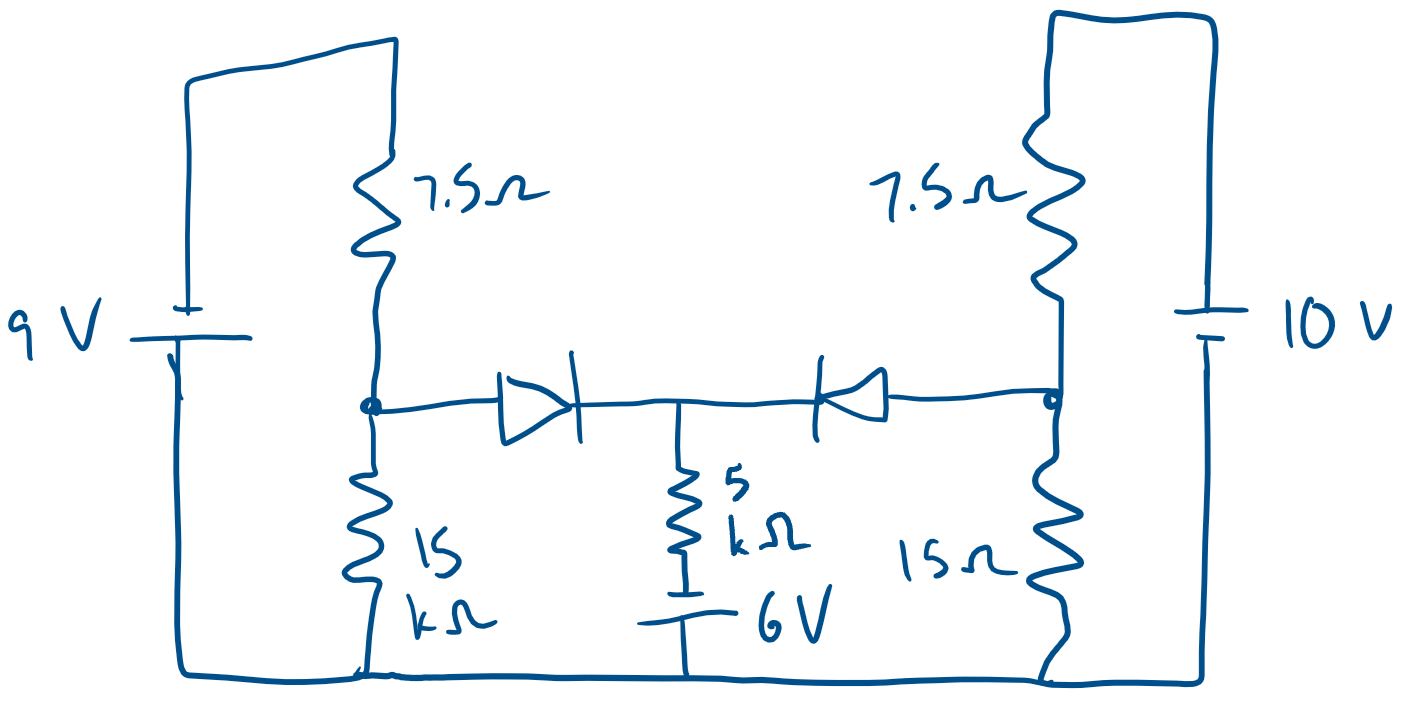
enter image description here Edit2: Diagram with common ground

enter image description here

\$\endgroup\$
4
  • \$\begingroup\$ "-9 V" means you assume there is a -9 V source connected between this node and ground. Once you draw in the sources, you have closed circuits like you are used to. \$\endgroup\$
    – The Photon
    Commented Oct 1, 2018 at 22:44
  • \$\begingroup\$ Would the representation in the edit above be correct? \$\endgroup\$
    – Eric
    Commented Oct 1, 2018 at 23:01
  • 1
    \$\begingroup\$ Not quite -- you need to tie all three grounds to one common rail on your schematic -- i.e. the positive side of that 9V source is common with the positive side of the 6V source and the negative side of the 10V source. \$\endgroup\$
    – TimWescott
    Commented Oct 1, 2018 at 23:08
  • \$\begingroup\$ Ah gotcha, so it seems like the easiest way to reconfigure these problems is to start with a common ground and connect the circuit appropriately from there. \$\endgroup\$
    – Eric
    Commented Oct 1, 2018 at 23:16

1 Answer 1

0
\$\begingroup\$

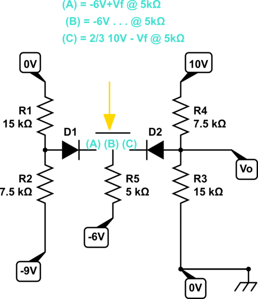
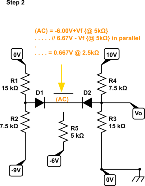
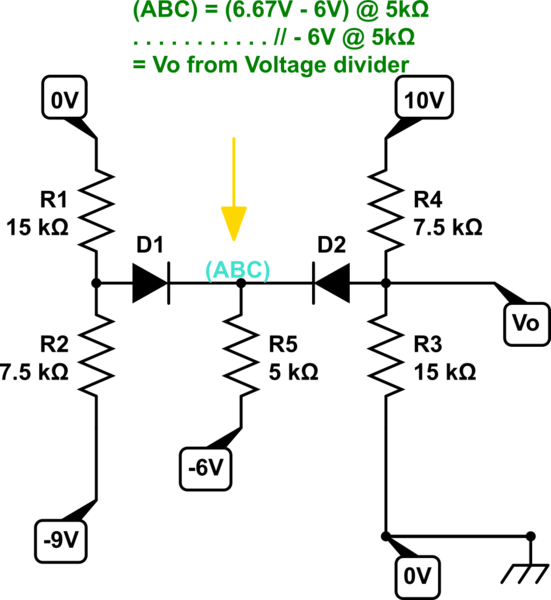
This is an intuitive way I can solve this in my head in << 1 minute. You may use KCL,KCL.

schematic

simulate this circuit – Schematic created using CircuitLab

schematic

simulate this circuit

schematic

simulate this circuit

\$\endgroup\$

Your Answer

By clicking “Post Your Answer”, you agree to our terms of service and acknowledge you have read our privacy policy.

Not the answer you're looking for? Browse other questions tagged or ask your own question.