1
\$\begingroup\$

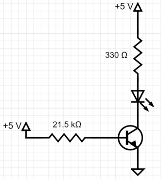
Circuit diagram

I've been trying to wrap my head around the current I measured through the collector branch vs. the expected calculation for collector current and believe I have a knowledge gap in what to do.

The setup of the circuit is shown above with the LED being a blue LED with a forward voltage given as 0.3 V which seems implausible to me.

To find the collector current \$i_C\$ I measured the voltage drop across the 330 ohm resistor as 1.9855V and calculated \$i_C=\frac{V_{RL}}{R_{L}}=1.9855/327\approx6mA\$.

From my prior calculations, I chose a base resistor that would give 20mA for my collector current with \$\beta=100\$ as a rough estimate as our beta is unknown but in the range of 100-300.

I'm not sure if my formula for collector current is incorrect as I'm expecting there to be quite a bit more current. I tried another method which I'm not sure is right where I did

\$i_C=\frac{V_s-V_f{_{LED}}-V_{C}}{327}=\frac{5-0.3-0.00985}{327}\approx14mA\$ Which was quite a bit higher than from my other calculation, however when I put the forward voltage of the LED at 3V and put it back into the equation, I get about 6mA. So I'm not quite sure if the forward voltage of the diode given is incorrect as 0.3 forward voltage seems extremely low for an LED or if my calculations are wrong.

I haven't learnt much about diodes or transistors besides a basic overview before this experiment so I'm quite confused on where to go from here.

\$\endgroup\$
7
  • \$\begingroup\$ Yes, the forward voltage should be more like 3 V for blue. Are you sure you didn't misread the saturation voltage (0.2 to 0.3 V) as the LED forward voltage? To turn the transistor hard into saturation you need to beef up the base current a lot more than the gain calculation suggests. Note also that the gain calculation breaks down once the transistor is saturated. The collector current is determined then only by the supply voltage and load. Stick at it! \$\endgroup\$
    – Transistor
    Commented Oct 20, 2018 at 1:55
  • \$\begingroup\$ We weren't able to use the diode checker on our DMM to read the forward voltage of the LED so we were told to use 0.3V. I'm going to assume it's more around 3V, thanks for the help \$\endgroup\$ Commented Oct 20, 2018 at 2:11
  • \$\begingroup\$ Classic design method for good saturation is to assume Beta/10, or 10 for this circuit/transistor. Use a 2.2Kohm in the base. \$\endgroup\$ Commented Oct 20, 2018 at 3:22
  • \$\begingroup\$ \$\beta=\frac{6\:\text{mA}}{\frac{5\:\text{V}-700\:\text{mV}}{21.5\:\text{k}\Omega}}\approx 30\$ from that circuit, given your measurements. This means the BJT is likely in light saturation. This suggests that your LED has \$5\:\text{V}-2\:\text{V}-400\:\text{mV}\approx 2.6\:\text{V}\$ when running at \$6\:\text{mA}\$. I'd tend to go with \$3\:\text{V}\$ as an estimate for the desired drop across the LED. If you want to stick with the \$\beta=30\$, you should use about \$80\:\Omega\$ instead of \$330\:\Omega\$ and thereby also reduce \$21.5\: \text{k}\Omega\$ to \$5.6\:\text{k}\Omega\$. \$\endgroup\$
    – jonk
    Commented Oct 20, 2018 at 3:54
  • \$\begingroup\$ But as others point out, probably better still to use a smaller saturation \$\beta\approx 10-15\$, I think. If you want some more explanation about putting a BJT into saturation, here is one link to read up on. This may help a lot in understanding what to do when trying to use a BJT as a switch, like this. \$\endgroup\$
    – jonk
    Commented Oct 20, 2018 at 3:56

0

Your Answer

By clicking “Post Your Answer”, you agree to our terms of service and acknowledge you have read our privacy policy.

Browse other questions tagged or ask your own question.