0
\$\begingroup\$

My son (9yrs) has become interested in robotics. I did a course on it in college, but that was a LOOONG time ago and the course was much more rooted in programming than it was in electrical engineering. So, I'm learning as I go so that I can keep the project as wrinkle-free as possible.

I know that pre-built options for what I'm building already exist... but I don't learn anything having someone else do it for me!

So... I wish to build a "dual stepper motor driver" (I'm sure there's a better name for it, but that's what comes to mind), I plan to take the main power source (12V) and push it through a 5V regulator to supply the logic, to make the board as "self contained" as possible, rather than rely on the Arduino for my 5V supply.

I've already got a 100uF cap across Vmot/gnd, but there's the 5V logic Vin/gnd.... should I put a decoupling cap on that, as well, since it's coming from the same power supply?

I'm inclined to believe "it's not needed but it's a good practice", but I wanted to ask and be sure.

As I understand it the idea is to provide a "current buffer" to protect against a sudden need for power which can in turn cause harmful voltage drop or noise, and the logic really wouldn't draw much in the way of current, all while the minimum voltage I expect to see from the battery is 11.7V near empty (still exceeding minimum that the regulator would need... right?).

\$\endgroup\$

1 Answer 1

0
\$\begingroup\$

I've already got a 100uF cap across Vmot/gnd, but there's the 5V logic Vin/gnd.... should I put a decoupling cap on that, as well, since it's coming from the same power supply?

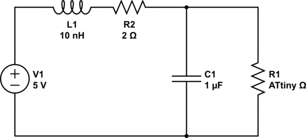
The caps function like a current 'buffer', they source current when it get's too low and sink current when it get's to high to maintain a constant voltage level. In the example below L1 and R2 represent the wire, C1 is a filter capacitor and R1 is a variable load.

enter image description here

The reason for using capacitors is the instantaneous current switching that circuits with millions of transistors can have and the other problem is that wires have resistance and inductance. If you could measure the inductance and resistance of the wires, you could actually tell how well of a filter you've built.

But for most of us we just 'ballpark' the capacitance, because that saves time. 100uF might be a little steep, and might increase the start up time but should be fine for your application. Digital lines are an important place to put caps on due to the variable nature of the load. Motors, especially stepper motors are another good place becasue they also switch, so I'd put caps on both.

\$\endgroup\$

Your Answer

By clicking “Post Your Answer”, you agree to our terms of service and acknowledge you have read our privacy policy.

Not the answer you're looking for? Browse other questions tagged or ask your own question.