0
\$\begingroup\$

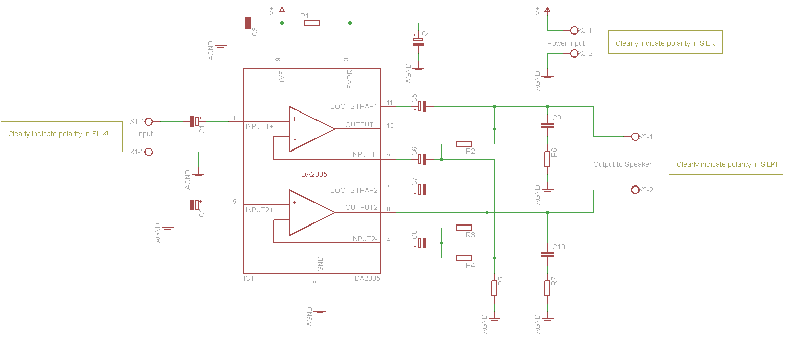
I'm designing a single sided board for a bridge audio amplifier based on TDA2005 (Datasheet). My circuit is the same as the one in Figure 3 in this datasheet. Schematic bellow:

Schematic

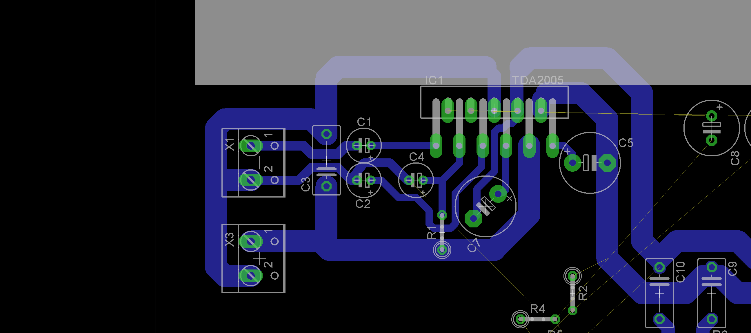
Here is a partial screenshot of my board so far. X1 is the audio input and X3 is the power supply input. C3 is the decoupling cap I'm worried about.

Board

I know from digital circuits that the decoupling caps must be the closest possible to the power pins on the IC. Is this required in (relatively low frequency) analog circuits as well?

I was trying to put the cap "between" the IC and the power supply, but the way it is now seems a bit far away from power pins. Also, the input signal is going under the cap and the power traces going to pins 6 and 9 are surrounding the input traces (and possibly the feedback circuitry in the future). I don't know if that is really a problem. Is it?

Another option I though was to put the cap near the output side, surrounding the output traces, but since they are too thick, I think it would be harder to layout the traces. Also, in this configuration, the cap would not be between the power supply and the IC (but after the IC).

Another question is if it is OK to connect X1's GND the way it is in the picture or is it better to put a separate trace to the GND connection in X3 an avoid sharing the GND trace between them?

I know there is a board example in the datasheet. I'm making this one for learning purposes.


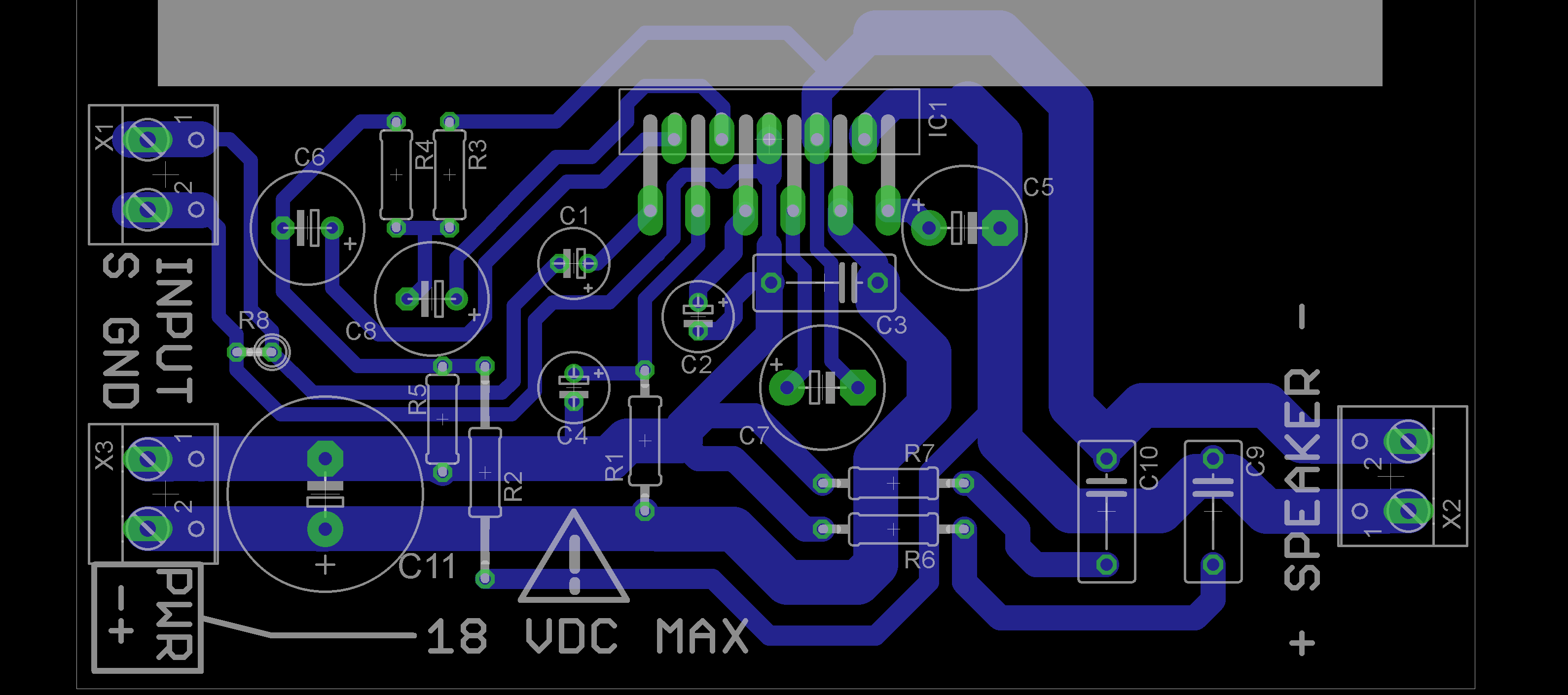
EDIT: Thanks for everyone who answered and commented to this question. I made some changes in the layout and kind of finished the board. Look the high resolution image below:

Final board

What I did:

  1. Following the advices of @Vladimir Cravero and @Scott Seidman, I added a 1M ohm resistor in the input and a 1000uF capacitor to the power bus.

  2. Put C3 closer to the Amplifier. Now, the power traces aren't surrounding the input and feedback circuitry. (Well, except by C7, which I didn't find another way to put it).

  3. I routed the GND signal from input to the GND pin in the IC. My intend was to isolate it from the currents going from the supply. Don't know if that is bad or good. I think it is OK to do that. Am I right?

I'm planning to "print" this board by tomorrow, to build the amplifier. Any thoughts or suggestions you want to make before I do that?

Thanks again!

\$\endgroup\$
2
  • \$\begingroup\$ Have a look at figure 4, you already get a (hopefully) working layout from ST, why bother spinning your own? Also, even if it's not in the TA schematic you probably must add some electrolytic big cap further away, that 100nF can provide for high f short pulses but is a sitting goose at lower frequencies. \$\endgroup\$ Commented Feb 28, 2016 at 10:32
  • \$\begingroup\$ @Vladimir I know about the example board. I want to make my own for learning. I will add a bigger capacitor to the circuit. Thanks. \$\endgroup\$ Commented Feb 28, 2016 at 14:12

2 Answers 2

1
\$\begingroup\$

Probably it will work. All effects are very small there.

Still, from best practices point of view, this not a good idea. The decoupling capacitor provides energy for current peaks, which for class D amplifier are pretty high.

Edit: yours is class B, so frequencies are low and hence effect are even lower.

So you will have a trace with varying voltage for capacitive coupling with the signal and pulsed currentl for inductive coupling. Either way the switching (edit: for class B audio) frequency will get to your input.

Why don't you use bottom side of the board for GND?

\$\endgroup\$
8
  • \$\begingroup\$ I intend to make this board at home, so one side only, unfortunately. \$\endgroup\$ Commented Feb 28, 2016 at 5:03
  • \$\begingroup\$ Then go for it. But better fins a chinese pcb production service, they are cheap and quick, and make as many layers as you need \$\endgroup\$
    – user76844
    Commented Feb 28, 2016 at 5:06
  • \$\begingroup\$ I used their services already. I know they're cheap and ship quickly, but the customs in my country aren't neither one of these. The taxes for importing are quite high and also the US dollar exchange ratio. I also like to do it myself, so, at least for the firs prototype, I will stick to doing it. :) \$\endgroup\$ Commented Feb 28, 2016 at 5:13
  • \$\begingroup\$ Good luck then! I am sure it will work well \$\endgroup\$
    – user76844
    Commented Feb 28, 2016 at 5:25
  • \$\begingroup\$ Well I am not. That layout can definitely be improved, and I have never heard a TDA 50Hz free, not on a homemade project. \$\endgroup\$ Commented Feb 28, 2016 at 10:34
0
\$\begingroup\$

It is bad practice to not provide a DC path from op amp inputs to give bias currents a place to go. You should have a large resistor to ground, or your op amp has a pretty good shot at saturating at one of the rails.

\$\endgroup\$
1
  • \$\begingroup\$ Thanks. I did that (look at my edit in the original question). \$\endgroup\$ Commented Feb 29, 2016 at 0:46

Your Answer

By clicking “Post Your Answer”, you agree to our terms of service and acknowledge you have read our privacy policy.

Not the answer you're looking for? Browse other questions tagged or ask your own question.