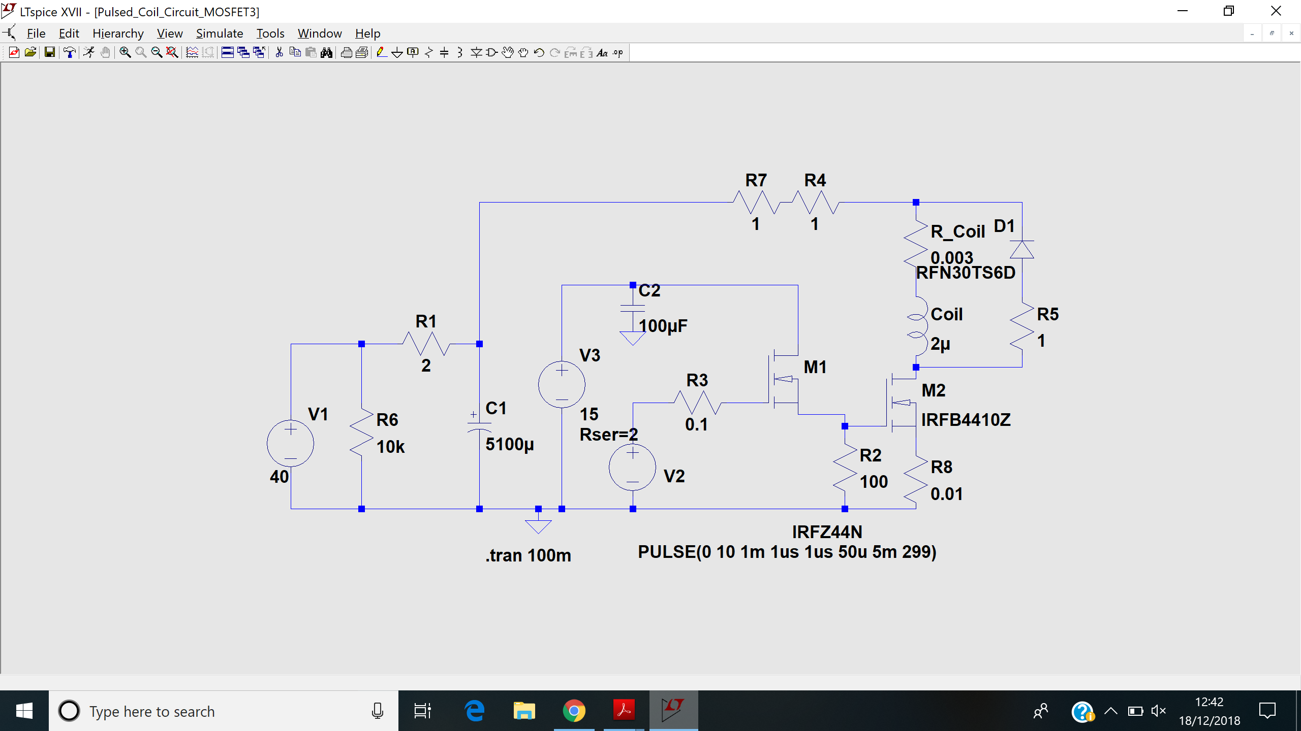
I have the following circuit,
I am using it to create a pulsed magnetic field, in the coil. I am trying to measure and verify the magnetic field in the coil. I am testing it with 40 V to drive the coil at the moment, which should provide 20 A of current to the coil and produce a 12.5 mT field within it. There are additional unwanted oscillations that are making things less straight forward for me.
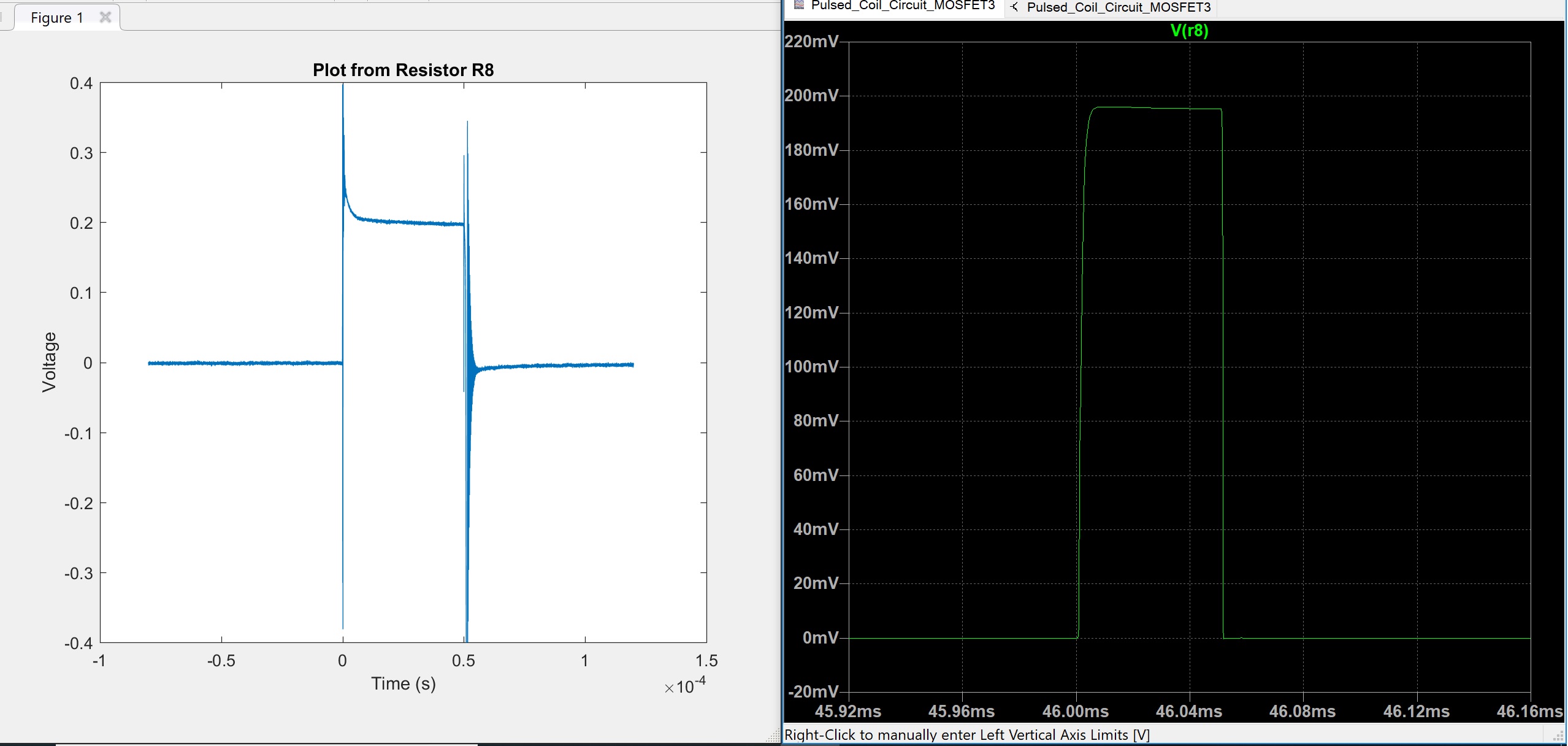
First I would like to verify the current going through the coil, so I included R8, to measure the voltage across it, to work out the pulsed current in the circuit.
The model result comes out a lot smoother, which is expected, as it is more ideal.
There is a lot more ringing/oscillations in my built circuit, but it comes out at just over 200 mV which indicates approximately 20 A of current.
I am curious about the large spike and oscillations, what might be causing this and how I might reduce these. Below I mention additional inductance that appears to be cause by the resistors R4 and R7, so this is a likely contributing factor.
Next I want to measure the magnetic field using a coil. Based on the design of the coil in the circuit, for 20 A of current it should theoretically produce a 12.5 mT B field.
Using a single turn loop, with an area of 1.29e-4 m^2 placed at the centre of the coil, the voltage should theoretically be V = -1.6125e-6/dt
based on V = -N dBA/dt
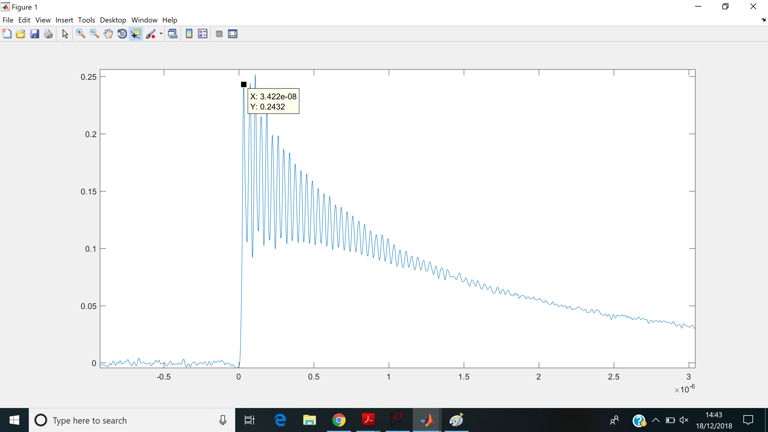
My plot of the loop voltage is
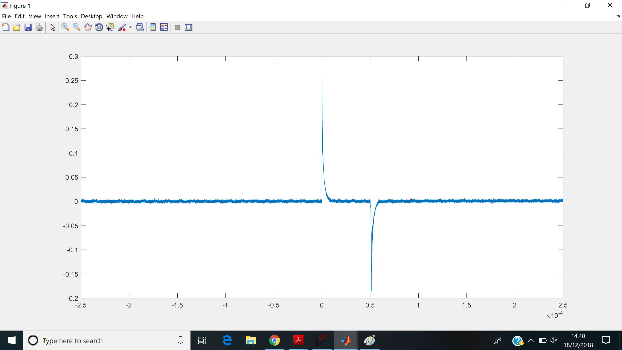
It spikes when the current goes on and off. However there is a lot of oscillation
If I use the first peak of the voltage, taking its time, the formula suggests a output voltage of 47 V needed for the 12.5 mT I expect, not the ~250 mV I am getting. So I have made a mistake somewhere or am missing something in my assumptions. The formula I am using I have typically seen for an oscillating field, but I thought it is applicable here also.
I would like to know where I am going wrong with my assumptions with the measurement coil, either theoretical or with my set up.
I noticed that the oscillations reduce further away from the initial spike if I touch the casing of R4 (and to some degree R3), which suggests they are adding an additional inductance to my circuit which is being reduced by the capacitance of my body as I touch it, and I have missed in the model.
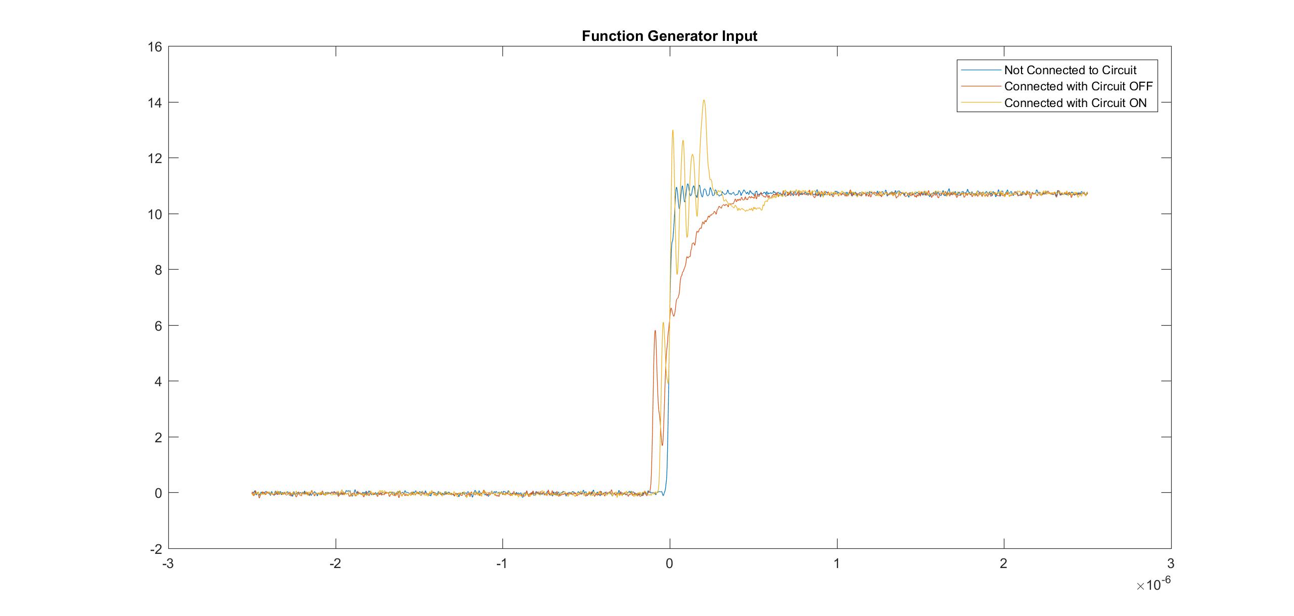
Also looking at my pulse signal to switch on/off M1, it is not quite a square pulse when it is connected to the circuit.
This graph shows what happens to my function generator signal as from what it is set to do, when connected to the circuit with V3 OFF, and with V3 ON. It kind of gets up to 6 V which is about where M2 should switch on and goes down before going up again.
Note that M2 in the model is not the same MOSFET as in my circuit, it is actually a IRFP260NPNF MOSFET, I am unable to model the exact one in the circuit simulation (still learning).
I am hoping for suggestions as to how I might improve my circuit and reduce unwanted oscillations, and to improve the method I am using to measure the magnetic field, and how I might be going wrong.

