0
\$\begingroup\$

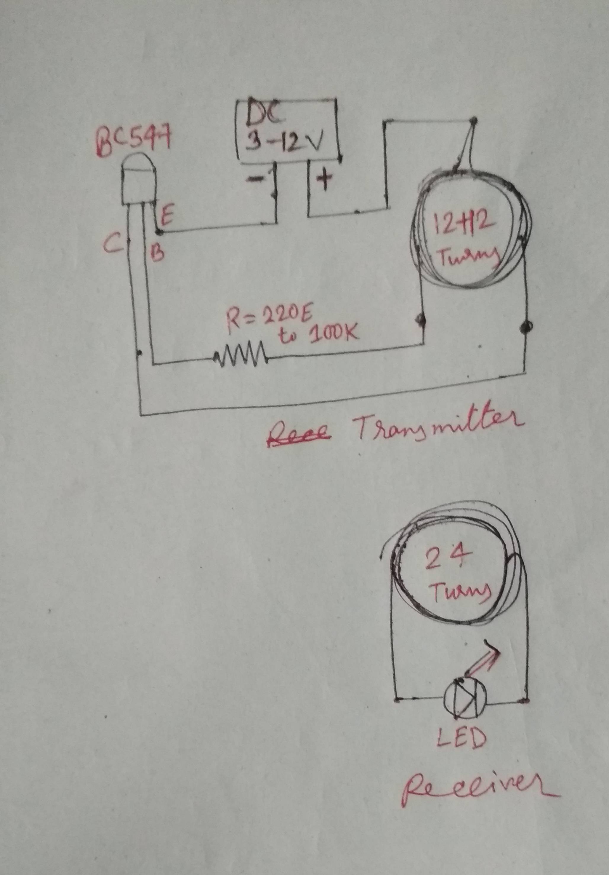
I made wireless electricity transmission model using the principle of magnetic inductive coupling to transfer electricity between two separate coils. The model is very simple, known to everyone and lot of resourses available in internet. My circuits are as bellow...


ciruit diagram

I am using BC547 transistor. The transmitter coil have 12 + 12 turns and receiver have 24 turns. Initially I started with DC 3.3v supply, 1.2k ohms resistor for base. Only one thing that i have no idea what is the awg of the magnet wire! I collected the wire from a small on board transformer from smps. I am using solder less breadboard.

But nothing happens. No electricity transmits ! I checked all the circuit diagrams. Tested continuity with multi meter. Everything was fine. I also tested the transistor and also changed with another piece. But nothing works. So then i switched the base resistor to 220 ohms through 100k many values but no result. Then I increased the supply to DC 5V and tried with many resistors. But still no result. Now the transistor started to get some hot.

Then I switched to 12 V DC. Now I can see a very little flash in led (brightness not more than 5 percent) for only about one tenth of a second. But this time the transistor becoming very much hot withing 3 seconds. So I disconnects switch immediately.

So where is the fault? I have found in internet this is working fine for others. Can anyone tell where is the problem? Please don't ask me to use other transistor, BC 547 working fine for others. So try to find the fault. Thnx in advance.

\$\endgroup\$
10
  • \$\begingroup\$ How far are you placing the coils? magnetic fields fall of with the distance cubed so this is very important \$\endgroup\$
    – Voltage Spike
    Commented May 17, 2019 at 17:44
  • \$\begingroup\$ @laptop2d i place the coils within 1 mm.. I tried from far to almost touch position . From all angle. \$\endgroup\$
    – user222203
    Commented May 17, 2019 at 17:46
  • \$\begingroup\$ Show the site where you found the circuit, \$\endgroup\$
    – Voltage Spike
    Commented May 17, 2019 at 17:49
  • \$\begingroup\$ i found it in many sites.. and many youtube videos \$\endgroup\$
    – user222203
    Commented May 17, 2019 at 17:50
  • \$\begingroup\$ do you have an oscilloscope? There isn't any way to know what your circuit is supposed to do from the crude diagram. You need to know the inductance of the coils at minimum \$\endgroup\$
    – Voltage Spike
    Commented May 17, 2019 at 17:51

2 Answers 2

1
\$\begingroup\$

The fault is in the coil, make the coil in the way it is supposed to be constructed. Make sure the resistor is sized correctly to the coil and it should work.

\$\endgroup\$
2
  • \$\begingroup\$ As i have said i tried with many resistor values from 220 to 100K. And the coil turns are also correct. \$\endgroup\$
    – user222203
    Commented May 17, 2019 at 18:01
  • \$\begingroup\$ i have doubt about the gauge of the wire. if that making some problem, \$\endgroup\$
    – user222203
    Commented May 17, 2019 at 18:01
1
\$\begingroup\$

The capacitance of the solderless breadboard may be causing your issues. This is a finicky circuit. The creators are proud that they can make this work with only a few parts, but real circuits have more parts for a reason, to make them work reliably.

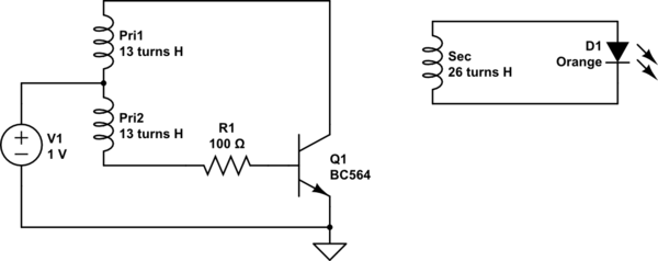
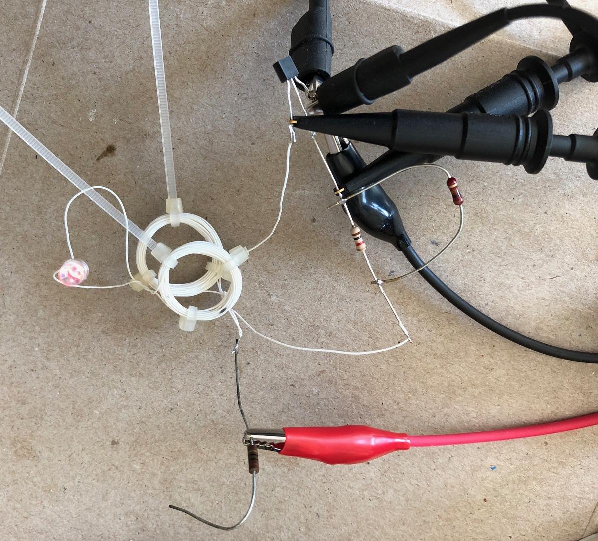
I was curious so I made the circuit. I used a BC546, basically the same as your transistor. My coil is 26 turns of 30 AWG solid wire, about 2 cm in diameter. I soldered the parts in mid-air. I started with a 1k base resistor. I set the current limit on my supply to 0.1 A, the rating of the transistor. It did not work. I lowered the base resistor to 100 ohms, it started working.

The supply current limits at 0.1A, ~1V!

The coils need to be within about 2 cm, with their axis (holes) aligned for the LED to light. Use a red, yellow, or orange LED since these have low voltage drops.

So, be sure that your coils are small. Don't use a solderless breadboard. Use a small PS voltage with the current limit set to 0.1A.

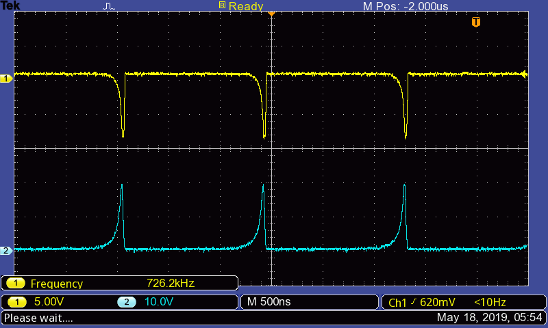
Channel 1 is the base voltage, channel 2 is the collector. Emitter is ground. The transistor is being stressed, the Vebo is being exceeded.

schematic

simulate this circuit – Schematic created using CircuitLab

enter image description here

enter image description here

\$\endgroup\$
3
  • \$\begingroup\$ Also, the LED is very dim, probably less than 1 mA average current. This is probably expected. \$\endgroup\$
    – Mattman944
    Commented May 18, 2019 at 2:24
  • \$\begingroup\$ Ok . .I will modify the circuit \$\endgroup\$
    – user222203
    Commented May 18, 2019 at 16:59
  • \$\begingroup\$ I'd imagine (possibly wrongly :-) ) that resonance with added capacitance large enough to swamp spurious capacitance would help repeatability. || Lonnnnnnng ago I made a multi drop inductive power transfer system. Inductors were wound reasonably dimensionally tightly but not overly so and 5% ? tolerance mylar caps were used. Spread of results was acceptable but some outliers were significantly low on output. \$\endgroup\$
    – Russell McMahon
    Commented May 19, 2019 at 13:59

Your Answer

By clicking “Post Your Answer”, you agree to our terms of service and acknowledge you have read our privacy policy.

Not the answer you're looking for? Browse other questions tagged or ask your own question.