0
\$\begingroup\$

I'm working on a fairly simple PCB that interconnects three arduinos. There are also MOSFETs for switching some solenoids. The system runs off of a 24V DC power supply. I was running a LM7812 voltage regulator, but I added a pair of cooling fans and they draw about an amp combined so I switched out the LM7812 for a R-78B12-2.0 DC-DC regulator.

I dropped in the 78B12 and everything looked fine. I ran the pair of fans for a couple of hours and everything seemed good. Nothing was warm, voltages were stable. I dropped in my arduinos and fired it back up and clearly something went wrong.

The trace from from 3.3uF input cap on the 78B12 to ground was smoked and the 78B12 is now shorting 24V straight out. That blew up one of my Arduinos and both of my cooling fans.

I'm not sure where to start to diagnose what happened and would appreciate the help.

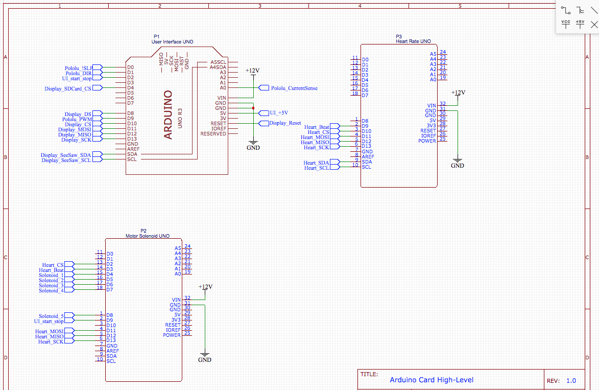
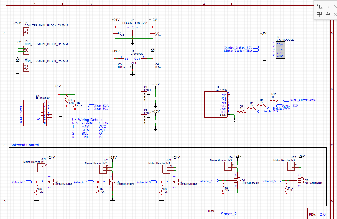
EDIT: Here are my schematics (with fixed ground on U6 and correct C1)

Schematic Page 1 Schematic Page 2

\$\endgroup\$
15
  • \$\begingroup\$ There is insufficient information about the circuit. You are going to have to provide a schematic before anyone can really help you. \$\endgroup\$
    – scorpdaddy
    Commented Jul 16, 2019 at 12:53
  • 1
    \$\begingroup\$ There is no 3.3uF input cap nor a 78B12, please show the complete circuit. Do you have protection diodes anti-parallel to the solenoids? \$\endgroup\$
    – Huisman
    Commented Jul 16, 2019 at 13:00
  • \$\begingroup\$ Why is the COM not connected on U6? Where are the 3u3 caps mentioned in your post? Was the burnt trace a series connection between source and load? \$\endgroup\$
    – Transistor
    Commented Jul 16, 2019 at 13:02
  • \$\begingroup\$ Just uploaded the schematics. U6 COM is connected. I just added the R78B12 to the schematic and didn't draw that wire. The burnt trace was the connection between the ground pin of the cap and ground. \$\endgroup\$
    – Adam
    Commented Jul 16, 2019 at 13:04
  • \$\begingroup\$ Boy, the input cap (C3) looks a little small (datasheet calls for something like a 4.7uF-10uF) and I am assuming that U6-2 is connected to GND. And, as Huisman stated about the flyback diodes for the inductive loads. \$\endgroup\$
    – Steve
    Commented Jul 16, 2019 at 13:06

1 Answer 1

1
\$\begingroup\$

Huisman was spot on. The issue was the improperly sized capacitor. Just posting this to close out the question.

Thanks!

\$\endgroup\$
1
  • \$\begingroup\$ Congrats with the solution. Good luck with the electronics! \$\endgroup\$
    – Huisman
    Commented Sep 17, 2019 at 17:19

Your Answer

By clicking “Post Your Answer”, you agree to our terms of service and acknowledge you have read our privacy policy.

Not the answer you're looking for? Browse other questions tagged or ask your own question.