1
\$\begingroup\$

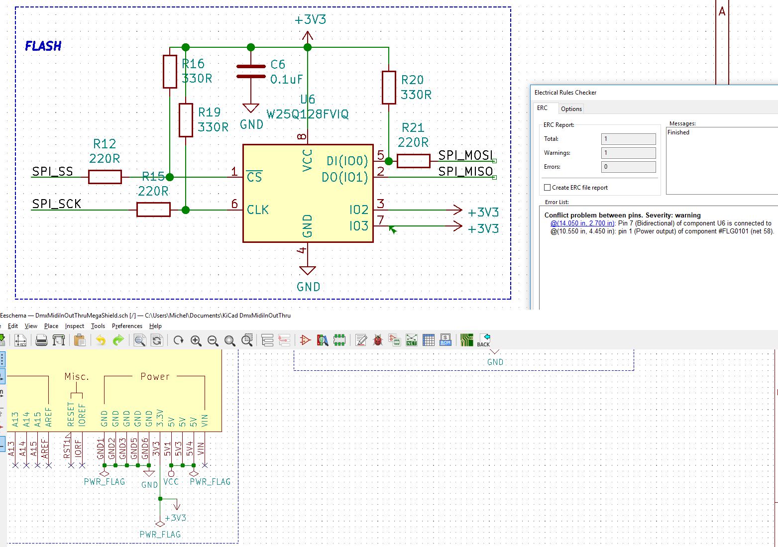
Below are parts of my design.

Using KiCad, I have problems using both VCC (5V) and 3.3V power, both from Arduino Mega pins.

If on U6 (flash) I connect 3 and 7 I get a similar error, so I guess I did something wrong regarding the PWR_FLAG settings. I also tried using the VCCQ (it also has a round symbol like VCC), but then I get different errors.

What should I change in my schematics to use both 3.3V and 5V without any ERC errors?

enter image description here

\$\endgroup\$

1 Answer 1

3
\$\begingroup\$

Those pins are defined as bidirectional in the part library, which means that they could sink current (by trying to set the pin to 0). So the ERC is -- quite correctly -- flagging it as a potential problem.

If you're absolutely positively never going to use those pins as I/O, then copy that part into a new library part and define the pins as inputs. It's probably safer, if you have the room, to pull those pins up through resistors (10k\$\Omega\$ is a nice round number). That way if someone messes up the software and sets the pins to I/O they'll just harmlessly pull their outputs low, at the cost of some supply current.

\$\endgroup\$
4
  • \$\begingroup\$ Thanks for your answer, but I don't understand the last part (why the pull up resistors are needed), since I will connect them to 3.3V and that pin is the Arduino Mega 3.3V pin, which cannot be programmed. Does this mean I do not have to use the resistors? \$\endgroup\$ Commented Aug 8, 2019 at 8:46
  • 1
    \$\begingroup\$ @MichelKeijzers because the pins of the W25Q128.. are I/O pins, if there is a mistake in the code, these could potentially pull the pin to GND. If you connect them directly to the Arduino 3V3, then you could cause an accidental short and damage parts in your circuit. Adding a 10k resistor is just protection in case that happens. Once you are certain you have it correct, these can be replaced for 0 ohm resistors, or the PCB redesigned without them \$\endgroup\$
    – MCG
    Commented Aug 8, 2019 at 10:24
  • 1
    \$\begingroup\$ @MCG Thanks ... that sounds good... I'm intending to first make a breadboard setup so I will test there with the resistor added; than I can leave it out on the PCB. I cannot 'redesign' it (I mean not order twice; would be quite some waste of money). \$\endgroup\$ Commented Aug 8, 2019 at 10:47
  • \$\begingroup\$ I added as you said the 10K resistors and now the error is gone too. Hope I don't get into problems with soldering (having not much experience). \$\endgroup\$ Commented Aug 8, 2019 at 22:13

Your Answer

By clicking “Post Your Answer”, you agree to our terms of service and acknowledge you have read our privacy policy.

Not the answer you're looking for? Browse other questions tagged or ask your own question.