0
\$\begingroup\$

I am generating a video signal using an AD724 and a microcontroller, which is genlocked to another video signal from a camera, and am using an SN74lVC2G53 analog switch to switch between signals.

I'm using a parallel bus 7 bits wide from a GPIO port, to control the switch and generate the RGB input to the AD724.

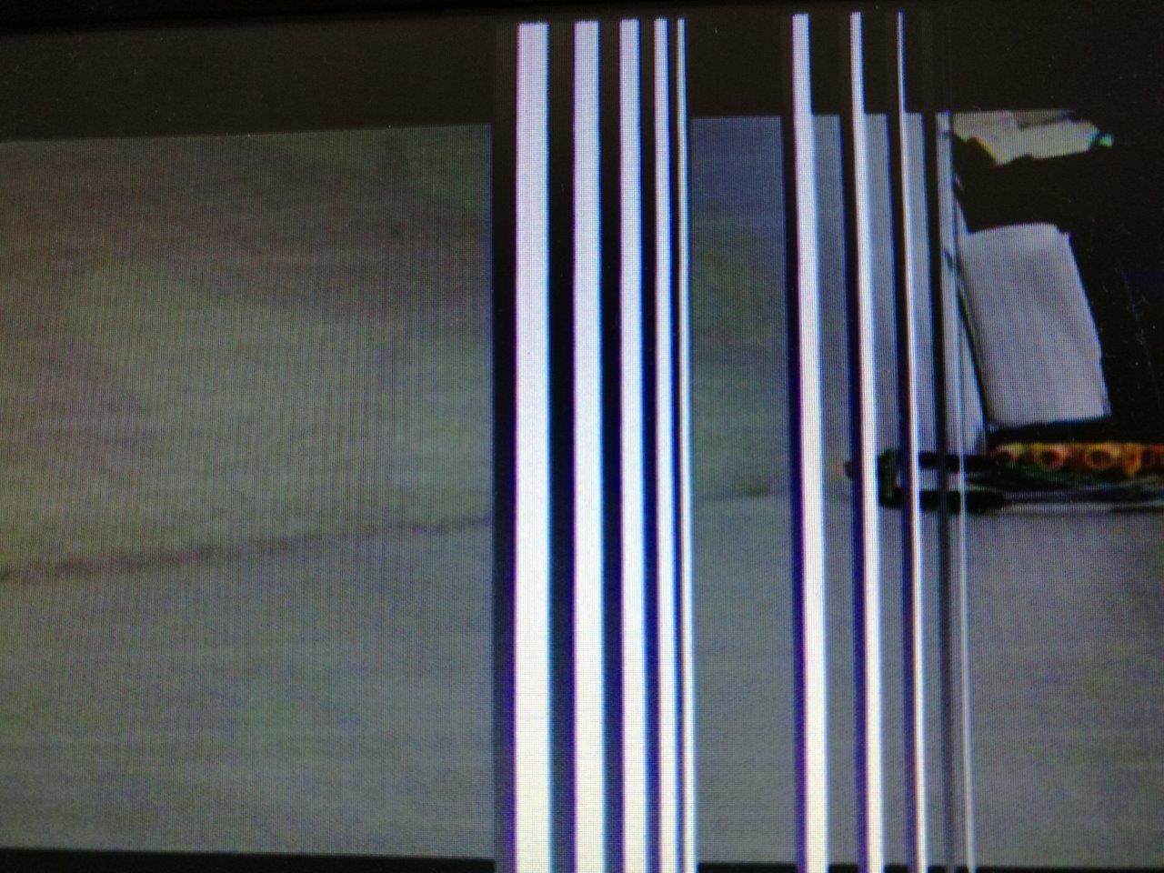
The issue I'm having is that the output from the AD724 is delayed relative to the output from the bus, I estimate the delay to be about 250 - 300nS. As a result, the overlay video is switched in and switched out "early" as you can see from this picture below where each of the 5 vertical bars to the right has a black shadow next to it. (Ignore the 5 bars to the left which is a single overlay and only switched once).

Overlay

I need to introduce a tunable delay to both the rising and falling edge of the switch signal, of around 250nS. I attempted to do this using an RC network. I found that 47pF / 4K gave approximately the correct delay, but since the delay is less than the switch toggle time in some cases, the capacitor doesn't fully charge and the switch doesn't activate. It's also introduced a blue "halo" effect, possibly because the signal isn't a sharp square edge anymore.

Overlay, RC delay

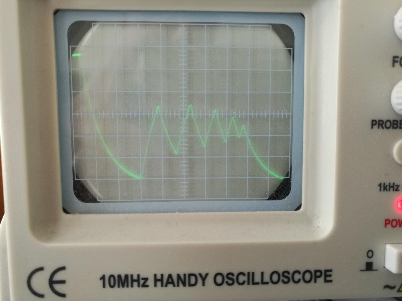
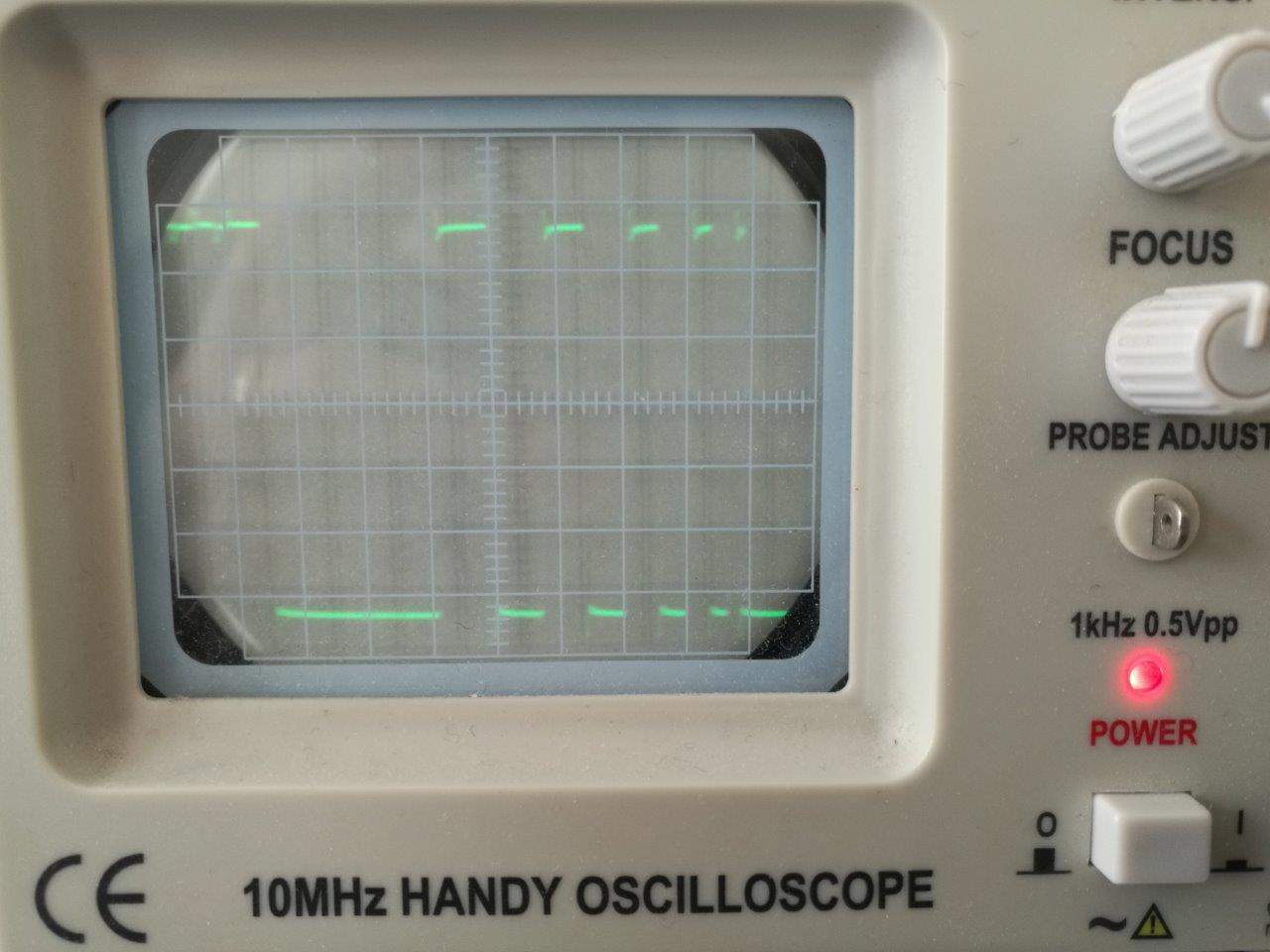
Here is a scope trace of the switch signal, delayed and undelayed.

Switch, RC delay, 1uS / div Switch, no delay, 1uS / div

My question: What is the best way to delay this TTL switch signal, while preserving the edges and voltage levels.

Best in this context would mean with the fewest number of components, ideally avoiding an extra IC on the board.

Edit I'm also open to doing it in software. I'm using an STM32F413. It seems it ought to be possible to use the SPI to drive the switch, and clock the SPI using a clock in sync with the pixel DMA but delayed. If only there were some clever way to have the SPI read only the 7th bit out of each byte in the frame buffer.

\$\endgroup\$
8
  • \$\begingroup\$ You can get logic-level delay lines, but that would constitute another "IC" on the board. Beyond that, I don't have a clear picture of what you're trying to accomplish. Switching at the output of the AD724 sounds like a bad idea, though. It would be better to convert the camera signal to RGB, do your overlay in RGB space, and then convert the combined signal using the AD724. Then the delays associated with the AD724 filters become a non-issue. \$\endgroup\$
    – Dave Tweed
    Commented Aug 16, 2019 at 22:36
  • 2
    \$\begingroup\$ When I worked in a TV studio (in a previous century) we had rolls of coax cable to adjust signal timing. (8" = 1 ns) \$\endgroup\$ Commented Aug 16, 2019 at 23:17
  • \$\begingroup\$ @Peter Bennet that certainly meets the criteria for few components but I wont have room for 260 feet of coax. \$\endgroup\$
    – Batperson
    Commented Aug 17, 2019 at 2:48
  • \$\begingroup\$ @David Tweed I hoped there might be a way using only passive components but if not I will use an IC. \$\endgroup\$
    – Batperson
    Commented Aug 17, 2019 at 2:52
  • 3
    \$\begingroup\$ get a Hex Schmidtt Trigger IC, and place 6 RC delays of 25 nanosecond between the Schmidtts. Use 100 ohm and 250pF, or 200 ohm and 125pF, or similar.Now you have 6 taps you can select; you can even make one cap be a variable. \$\endgroup\$ Commented Aug 17, 2019 at 3:58

1 Answer 1

1
\$\begingroup\$

You can use a logic delay line. This Maxim part ought to do it: https://www.maximintegrated.com/en/products/analog/clock-generation-distribution/DS1100.html

Another idea. If you have a common clock that makes the sync timebase (say, 4*Fsc), and it's common with your GPIO timebase that makes your RGB (it would have to be, right?), could you delay the mux signal using flip-flops?

\$\endgroup\$
3
  • \$\begingroup\$ Thanks @hacktastical. That seems like the best alternative so far. \$\endgroup\$
    – Batperson
    Commented Aug 17, 2019 at 5:52
  • 1
    \$\begingroup\$ I think the DS1100 is obsolete. Try this one, the 500ns one is in stock at Mouser: maximintegrated.com/en/products/analog/… \$\endgroup\$ Commented Aug 17, 2019 at 6:02
  • \$\begingroup\$ Changing to a comment as per @hacktastical's suggestion. One way to do it in software would be to utilize another DMA channel, pointing from the frame buffer to a different GPIO port. Configure the pin corresponding to bit 7 (the switch) as an output pin. Drive the DMA channel by a clock with the same overflow as the pixel clock, but started an arbitrary number of ticks later (slave mode). \$\endgroup\$
    – Batperson
    Commented Aug 17, 2019 at 23:21

Your Answer

By clicking “Post Your Answer”, you agree to our terms of service and acknowledge you have read our privacy policy.

Not the answer you're looking for? Browse other questions tagged or ask your own question.