0
\$\begingroup\$

I have an active low circuit. I'd like to delay the low signal input when the it gets tied to ground, but allow the input to come up instantaneously when the ground is released.

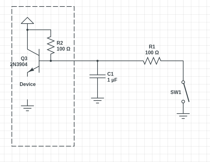
I've tried adding a capacitor in parallel with the input with a resistor in series with the input on the switch side of the capacitor.

Something like this..

enter image description here

I've also tried moving the resistor around.. and done a few variations of this and nothing seems to be working. I feel like this is something so simple that I'm missing. the component value in the drawing are not accurate to what I tried but i've tried as high as a 22uf cap and 2.7K resistor.

This whole idea seems to be working backwards. I'm getting a delayed high signal and fast low signal.

\$\endgroup\$

3 Answers 3

1
\$\begingroup\$

The problem with your transistor circuit is that you have created an emitter follower for the device connected at your output. This means that there can never be a saturated base current turning the transistor on and, as soon as you the close the switch you are reducing the base voltage by discharging the capacitor and immediately you see this reflected on the emitter. This is why it's called an emitter follower.

Ideally you would use an emitter that is grounded and put the "device" in the collector and up to Vcc. I would aldo use a changeover contact to remove the capacitor charging resistor and replace it with a grounding resistor. In other words have the capacitor fed by a charging resistor or a discharging resistor but not both at the same time.

\$\endgroup\$
0
\$\begingroup\$

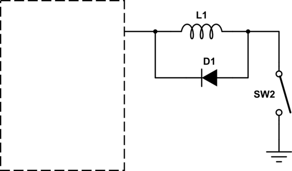
This will delay low while passing high quickly, when high has a high impedance and low a low impedance. in practice it may requite very large inductors, depending on the time scale involved.

schematic

simulate this circuit – Schematic created using CircuitLab

\$\endgroup\$
2
  • \$\begingroup\$ I need to get about a 0.2 second delay at 5v. Why not use a capacitor somehow? I'm still confused as to why my original circuit is working opposite of what I expected. Can you explain? \$\endgroup\$ Commented Jul 21, 2018 at 21:07
  • \$\begingroup\$ for capacitors current must flow, you can't make current flow by opening a switch. \$\endgroup\$ Commented Jul 21, 2018 at 21:18
0
\$\begingroup\$

My design actually works just fine. Due to an internal resistance in the device I'm working with, my timings were thrown off. After playing with the capacitor and resistor values, I was able to get the device to operate with a 47K resistor and a 1uF cap.

\$\endgroup\$

Your Answer

By clicking “Post Your Answer”, you agree to our terms of service and acknowledge you have read our privacy policy.

Not the answer you're looking for? Browse other questions tagged or ask your own question.