1
\$\begingroup\$

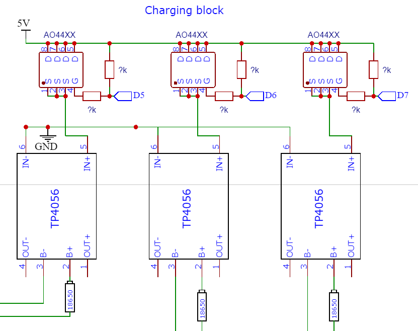
I'm quite confused about the p channel mosfet as a switch. I saw designs with zener diodes, other mosfets or BJTs but these seem overcomplicated. I have many P channel mosfets from broken chargers (mainly Alpha Omega 4407A, 4411, 4423 - which one should I choose?), that's the only reason I want to use the PMOS instead of NMOS.

I want to create a battery tester with charging and discharging capabilities. The only part that I don't know how to do is the power switching.

3V3 logic level with ESP8266 MCU, 5V charging voltage and 4.2-3V 18650 discharge voltage.
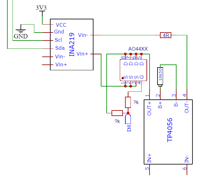
The prelimenary circuit: Charging block

Discharging block Is the circuit correct, do I need pullups? What values should I use for the resistors?

\$\endgroup\$
1
  • \$\begingroup\$ Your sources and drains are reversed. Source connects to power, drain connects to load, just like with an NMOS on the low side. As drawn, your loads will constantly receive power through the body diodes of your FETs. \$\endgroup\$
    – The Photon
    Commented Oct 3, 2019 at 18:06

1 Answer 1

1
\$\begingroup\$

Your circuit, even if the MOSFETs were correctly connected (S/D swapped) will not work because the gate voltage must be 5v (or very close to that) to turn the MOSFET off, and at least 0.5V to guarantee it is fully turned on (depending on the MOSFET out of the group you mention) and the ESP chip can only supply 3.3V so there is not enough swing to use a zener type circuit and you would need a level shifting stage (eg. a 2N7002 and pullup resistor).

schematic

simulate this circuit – Schematic created using CircuitLab

This circuit can be used with a MOSFET with 4.5V or lower Vgs for acceptable Rds(on).

\$\endgroup\$
2
  • 2
    \$\begingroup\$ I just went to say that. I see you've said it. I won't :-) . \$\endgroup\$
    – Russell McMahon
    Commented Oct 3, 2019 at 18:50
  • \$\begingroup\$ @RussellMcMahon Glad you saw it first and avoided duplication/irritation. With a 2.5V MOSFET and a bit of cheating (on very weakly pulling the output above 3.3) a green LED + pullup resistor could work, and indication comes for free. \$\endgroup\$ Commented Oct 3, 2019 at 19:10

Your Answer

By clicking “Post Your Answer”, you agree to our terms of service and acknowledge you have read our privacy policy.

Not the answer you're looking for? Browse other questions tagged or ask your own question.