1
\$\begingroup\$

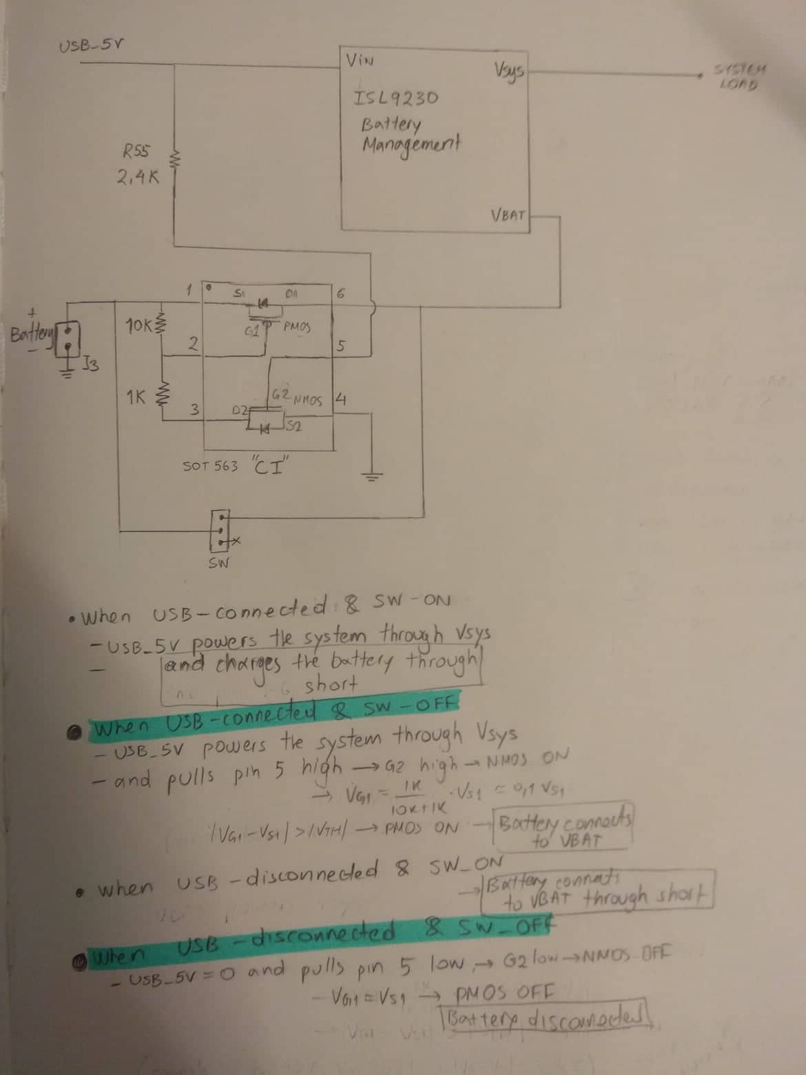
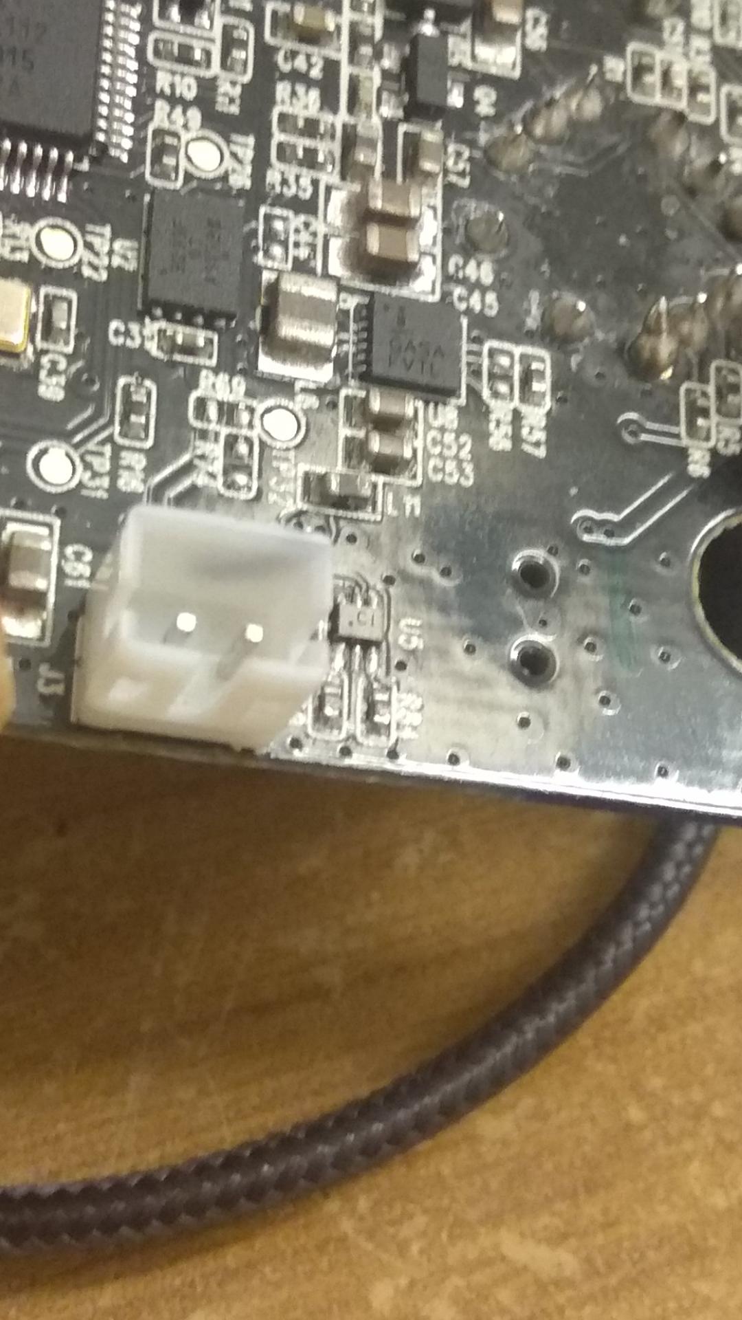
The IC (descriptor U5) with its peripheral resistors (R55, R84, R59) is right next to the battery connector, on the path prior to connecting to the battery charger IC (which is the ISL9230). The IC is marked "CI" and it is a SOT563-6 package (1.6mm x 1.6mm x 0.6mm). The schematic of the circuitry around the IC, as well as an educated guess about the internals of the IC are drawn below.

photo of PCB

final schematic

The circuit is from a wireless mouse that charges with a USB connector. I've seen designs that use one or two PMOS's and a zener diode for reverse polarity protection and I've also used dual channel mosfets in the past that come into a SOT-563 package. So my current guess is that the "CI" marked IC is a P-channel, N-channel MOSFET that is connectd like in the drawn schematic. By probing the body diode of the NMOS at the bottom I read 0.7V forward bias from S2 to D2. Also, when the USB cable is connected, G2 is pulled high and VD2 (pin 3) is equal to VS2, which is ground. So I'm convinced that this is the NMOS. As for the PMOS above, I also measure around 0.8V forward voltage across VD1 (pin 6) and VS1 (pin 1), so I assume this is the PMOS.

I am pretty sure the function of this IC is to isolate the battery from the rest of the system when the SW is off and the USB is disconnected.

The problem is:

  1. I've searched all of the P&N channel MOSFETS in this packeage from the digikey abd mouser library and none of them are market "CI". SI1024x-T1 from Vishay has a "C" marking but it's a dual N-channel MOSFET.

  2. All, literally all the N &P channel MOSFETS I've searched have the NMOS at the top (pins 1,2,6) and the PMOS at the bottom (pins 3,4,5), which is complementary to the internal circuitry I've drawn for the IC.

So my question is if the internal circuitry I've drawn is correct or is this a different type of IC than I initially thought.

Ideally, I am looking for the part number of this specific IC marked with "CI". But I will also accept any answer that explains what type of IC that would be (dual NMOS/dual PMOS/NMOS&PMOS etc) and what its purpose is.

\$\endgroup\$
14
  • 1
    \$\begingroup\$ Hmm are you sure that bypass link between mysterious IC's pins 1 and 6 is there? Having it seems to mostly defeat any purpose the IC might have... \$\endgroup\$
    – anrieff
    Commented Nov 27, 2020 at 19:55
  • 2
    \$\begingroup\$ Are there no numbers on the IC? \$\endgroup\$ Commented Nov 27, 2020 at 20:41
  • 1
    \$\begingroup\$ Please show said CI with a clear photo. \$\endgroup\$
    – winny
    Commented Nov 28, 2020 at 0:13
  • 2
    \$\begingroup\$ @George, wrt edits: it seems the mysterious IC only serves real purpose when the SW is off, and there is USB power. Maybe some sort of "when the battery is completely charged, stop charging current if the mouse is off". Could be just a comparator / power supervisor. Can you check what happens if: SW is off, USB power ON, battery level 4.2V, and then repeat with battery level e.g. 3.7V? \$\endgroup\$
    – anrieff
    Commented Nov 28, 2020 at 11:07
  • 1
    \$\begingroup\$ Find out which capsule that is with a caliper and start searching. CI, known capsule, known pinout and possibly the application note for ISL9230 should narrow it down. Also, for future reference your dual corner “connection” of pin 1 in your hand drawn schematic is not allowed. \$\endgroup\$
    – winny
    Commented Nov 28, 2020 at 11:11

2 Answers 2

1
\$\begingroup\$

Since the IC can’t interrupt the battery power, logically it must have some other function than for battery protection. I’m not familiar with the ISL9230 but perhaps it’s there to provide some kind of bootstrap facility if the 9230 cuts off the battery (low voltage or overcurrent perhaps)?

\$\endgroup\$
1
  • \$\begingroup\$ Thanks. Wondering if you've seen the edits. There is actually a switch between pin 1 and 6 which probably means that this IC is there for the instance when the user decides to turn off the switch and operate with USB maybe... \$\endgroup\$
    – Geo
    Commented Nov 28, 2020 at 0:29
0
\$\begingroup\$

After relentless searching I am now 99% sure I have found the IC. It's the PBLS1501Y prebiased 1NPN 1PNP. My 1% doubt is that it's not marked with "CI" based on the datasheet, but with "C1". That's pretty close (but if you find one with "CI" anywhere do let me know).

It was found by initially filtering my searches for MOSFET arrays (N&P channel) with the SOT563 packaging based on the analysis in my initial question. However, as I mentioned before none of the MOSFET arrays I searched for had their pmos at the top (between pins 1 and 6) and the nmos at the bottom (between pins 3 and 4). And therefore, after anrieff's suggestion to search for BJT's as well, the PBLS1501Y was the only one that happens to have the PNP and NPN oriented the correct way -correct in order for my analysis to make sense. And apparently, the external resistors R84, R59 are there to bias the PNP (the NPN is internally biased).

\$\endgroup\$

Your Answer

By clicking “Post Your Answer”, you agree to our terms of service and acknowledge you have read our privacy policy.

Not the answer you're looking for? Browse other questions tagged or ask your own question.