0
\$\begingroup\$

I am try to understand how to read data from current transformer circuit. As reference i am reading on this 2 articles: Article1 and Article2. I do not have easy access to oscilloscope which make it a bit harder for me to visualize.

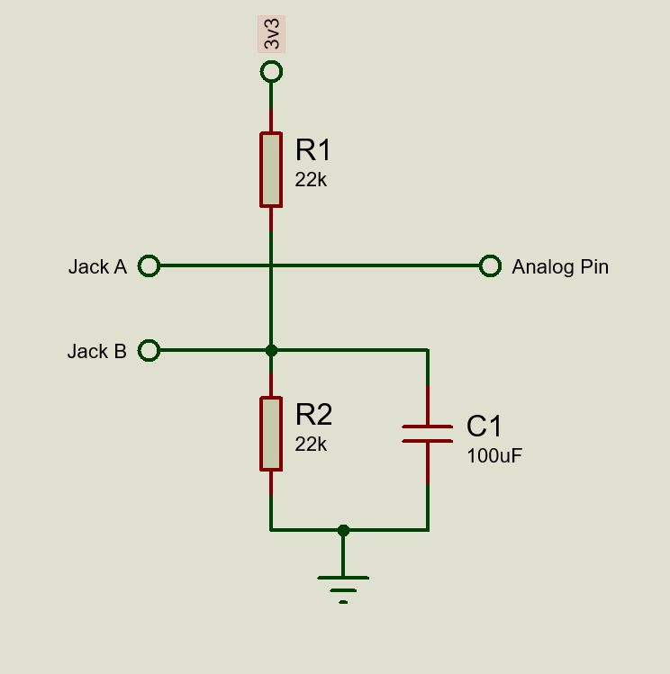
Here is the circuit that Article one and two uses. (PS i am assuming the version where the burden resistor is built in to the sensor already)

enter image description here

What is the purpose of the Equal value resistor voltage divider and the capacitor? How would i compute the resistor and capacitor value?

what would be the reading if probes are directly connected to JACK A and B

\$\endgroup\$

1 Answer 1

0
\$\begingroup\$

The resistor divider is used for making a reference voltage. When no voltage difference is present between A and B, you get half of Vcc on the analog pin - say 1.65V. When the voltage difference A-B is positive you get more than 1.65V on analog pin, meanwhile when voltage A-B is negative you get less than 1.65V.

Between A and B you have to connect a burden resistor, then a CT.

What is the purpose of the Equal value resistor voltage divider and the capacitor? How would i compute the resistor and capacitor value?

Leave it the same. If it works for others, it will work for you, also.

what would be the reading if probes are directly connected to JACK A and B
Don't quite understand this question.

\$\endgroup\$
1
  • \$\begingroup\$ What would happen if i directly read the analog pin on Jack A and connect Jack B to ground? \$\endgroup\$
    – Jake quin
    Commented Oct 16, 2019 at 13:53

Your Answer

By clicking “Post Your Answer”, you agree to our terms of service and acknowledge you have read our privacy policy.

Not the answer you're looking for? Browse other questions tagged or ask your own question.