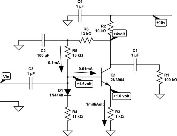
This circuit will give you 1MHz bandwidth, and drive a 100Kohm load with less than 10% error because of the load resistor.
Your gain (notice I made this YOUR circuit) will be 10K||13K / (1K + 26 ohms)
where the 26 ohms is the small_signal gradient of the diode equation for certain
diode dopings, also useful for transistor transconductance thinking.

simulate this circuit – Schematic created using CircuitLab
What dos this schematic illustrate?
--- the 100K load resistor is 10x the Collector resistor, thus there is less than 1 dB gain error (1dB = 12% voltage ratio)
--- the bandwidth (at the collector), with NO ALLOWANCE for any Cload across the 100Kohm, is approx. 10Kohm in parallel with 10picoFarad, the Cob of 2N3904 (from my memory). In truth we should include the DC_biasing feedback resistor of 13K to be in parallel with the 10K. Ignoring that for now, as we
approximate the collector TAU to arrive at the bandwidth, we have 10K ohm * 10pF = 100 nanosecond. Since this is a 1-pole approximation, just invert that and divide by 6.28 to have bandwidth being 1.59MHz.
--- the gain is roughly Rcollector/Remitter (10Kohm/1Kohm); for more accuracy, read the 2nd paragraph of this answer
--- input resistance? so you might compute loading effects on any sensor or voltage source such as a prior stage? R4 || R5 || (Beta * R3)
--- input impedance? Cmiller will make the Cin be (1 + Av) * 10pF; you can cascode this circuit, and reduce that to (1 + 1) * 10pF
--- distortion? if I recall rightly, 4 milliVolts across the emitter-base will produce 10% distortion of collector current; however there is a linearization resistor in the emitter, of value 1,000 ohms. The ratio of 1,000 / 26 is the distortion-improvement ratio, which is 39:1. Thus the distortion for 4 milliVolts input (across EB and Remitter) will be 10% / 39 or 0.25%.
Again this is for 4 milliVolts input. For fun, set up a SPICE simulation, alter the Vin to be 4mVPP, include .fourier behavior, and examine the result.

