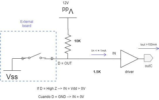
I have this circuit for getting 12V or 0V from external control signals. Signals will arrive by pin connector to my board. Switches will also be out of this board.
External control signal could be high Z or GND, depending on switch state.
I Would like to bring control signals (HZ/0V) from connector to the drivers: ULN2803.
- When input = HZ the idea is that driver output 0V, this is my proposal.
- So when input = GND --> driver output must be 12V.
This is what I need and this driver can achieve this behavior.
I can see how my first circuit stage do:
a) When D = HZ, current goes from vdd source to driver GND because it will be ON.
b) When D = 0, current goes from from vss to vdd source (being switch on, of course).
1) But I would like tu design the previous stage correctly and efficiently. Is it any better option for connecting the external control signals to the driver?
2) Someone told me about the need of buffers before driver. I'm asking if this circuit could really need some buffering devices and what kind of buffer could fit better here in this application.

