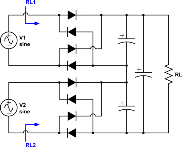
I want to rectify multiple isolated AC signals (Generated from multiple wireless power receiving coils) to a single DC load. For example, consider the following the schematic with two voltage sources \$V_1\$ and \$V_2\$ representing two wireless power receiving coils. \$V_1\$ and \$V_2\$ are at the same frequency (say around \$500~\rm{kHz}\$) and same phase.

simulate this circuit – Schematic created using CircuitLab
Question One:(solved more or less from the answer by @AndyAka and the other comments)
- Will this circuit works even if the magnitudes of \$V_1\$ and \$V_2\$ vary significantly? For instance, the magnitude of both sources can vary between \$5\$ V to \$20\$V independently. Is there any better topology?
Question Two
2. How do we calculate effective AC load impedances seen by two sources (i.e. \$R_{L1}\$ and \$R_{L2}\$)?
For example, if we have a single rectifier, we know its equivalent ac-side impedance is \$\frac{\pi^2 R_L}{8}\$[reference]. Now the question is, how can we calculate the equivalent impedance seen by two AC sides (see schematic \$R_{L1}\$ and \$R_{L2}\$)?
Here is my approach so far: Both ac links will have the same current. Therefore, equivalent load impedances should be proportional to the voltages, i.e. \$\frac{R_{L1}}{R_{L2}}=\frac{V_1}{V_2}\$. But what will be their values? is \$R_{L1}+R_{L2}=\dfrac{\pi^2 R_L}{8}\$? If this way of calculation is correct, I have another problem because of my \$V_1\$ and \$V_2\$ also dependent on the equivalent load impedances \$R_{L1}\$ and \$R_{L2}\$. In this case, do I have to use an iterative method to solve this problem?
