0
\$\begingroup\$

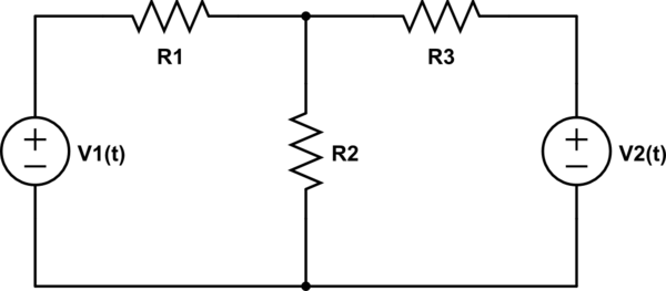
schematic

simulate this circuit – Schematic created using CircuitLab

My current understand is, for superposition (V1 and V2 acting alone) to be used in the circuit above to calculate the energy dissipated over a given resistor, the following must apply:

$$\int_{T_1}^{T_2} v_1\cdot v_2 \cdot dt \equiv 0$$

Is there an equivalent for current sources, i.e. replacing V1(t) and V2(t) by I1(t) and I2(t)?

P.S. Is that last dot product (with dt) a typo?

\$\endgroup\$
2
  • 1
    \$\begingroup\$ It's the same formula with i replacing v. \$\endgroup\$
    – Andy aka
    Commented May 31, 2020 at 13:16
  • 1
    \$\begingroup\$ Following @carloc and jonk's discussion below, the condition above can also be stated as: $$v_1(t)\circ v_2(t) = \int_{T_1}^{T_2}v_1 v_2 dt \equiv 0$$ Similarly, to fully answer the question, $$i_1(t)\circ i_2(t) = \int_{T_1}^{T_2}i_1 i_2 dt \equiv 0$$ \$\endgroup\$
    – cccube
    Commented Jun 1, 2020 at 11:41

2 Answers 2

2
\$\begingroup\$

Yes.

Couple of things:

generally at every moment the power dissipated in a resistor R is (i(t)^2)R where i is the current. If i happens to be the sum of two components a and b caused by 2 separate sources in a linear circuit, the power is ((a+b)^2)R.

Expanding the square of the sum gives the power = (a^2+2ab+b^2)R.

Dissipated energy in a certain time interval can be got by integrating. The integral really gives a sum of the separate energies of a and b if the product ab as integrated happens to give zero.

In communication signal calculations we often sum the powers of non-dependent sources or the squares of the RMS voltages just for this reason. The non-dependency means zero correlation which is the same as your "integral of the product must be zero" -rule.

The independency must be true for the summed current components that are caused by different sources. It's a well known case when the independency of the sources doesn't imply the independency of the current components in a load. That happens when 2 sources have a common point frequency component which just at the sources have 90 degrees phase shift. At load the phase difference can be different and that destroys the independence.

BTW The dot in the integral in the question means multiplication of scalar quantities. It's not an error. But often it's left out because we are used to present multiplication with no operator. In exact rigorous math the dot in front of dt is meaningless. The integration symbol doesn't present any multiplication by some infinitely small dt, the t after d only remember us that t is the integration variable. Mr Gauss, Mr Cauchy and Mr Riemann removed all mystical infinitely small quantities from integration and presented it as a logically acceptable limit process. Many famous mathematicians before them really used infinitely small quantities in their work.
\$\endgroup\$
8
  • \$\begingroup\$ As far as the notation is concerned I believe the dot shouldn't be inside the integral. What is a scalar product is the whole integral, so it would be right to write v1 dot v2=0 meaning integral v1 times v2 in dt=0 \$\endgroup\$
    – carloc
    Commented May 31, 2020 at 14:15
  • \$\begingroup\$ @carloc Why do suggest "in dt=0?" dt is infinitely small, but it is not zero (unless the range over which the integral is performed is also 0.) \$\endgroup\$
    – jonk
    Commented May 31, 2020 at 18:07
  • \$\begingroup\$ @jonk I understand what I wrote would have needed Latex and is then rather obscure. I was not referring to dt only but to the whole integral as posted by the OP $$ \int v_1 v_2 \mathrm{d}t =0 $$ But seems I finally can manage Latex from my mobile \$\endgroup\$
    – carloc
    Commented May 31, 2020 at 18:19
  • \$\begingroup\$ @carloc Oh. So, the case where: \$\int_{T_1}^{T_2} V_1\cdot V_2\:\text{d} t=0\$? I guess what also confused me is this part of your comment: "as far as the notation is concerned I believe the dot shouldn't be inside the integral." It really doesn't matter at all if you write \$\int_{T_1}^{T_2} V_1\cdot V_2\:\text{d} t\$ or write \$\int_{T_1}^{T_2} \left(V_1\cdot V_2\cdot \text{d} t\right)\$. Those are exactly the same thing. I thought maybe you were saying otherwise, but was not sure. \$\endgroup\$
    – jonk
    Commented May 31, 2020 at 18:26
  • 1
    \$\begingroup\$ @jonk what I was trying to say is I'd rather try to avoid using the dot for the plain multiplication. I try to reserve the dot for the scalar product. On the other hand I believe the above integral is a scalar product on some appropriate (Hilbert's) space. So what I'd written is something like $$ v_1\cdot v_2 = \int v_1 v_2 \mathrm{d}t = 0 $$ However the ambiguity of use of the dot is a well established practice, no concerns about it. \$\endgroup\$
    – carloc
    Commented May 31, 2020 at 19:49
2
\$\begingroup\$

No.

Couple of things:

Superposition applies to currents and voltages, and you must actually calculate the sum of these to calculate power: for example, in this very simple circuit, 0 A flow through the resistor, and hence 0 W is dissipated. If you switch on only either current source, 1 W will be dissipated. But the sum of these two powers (2 W) is not 0 W.

Logically, superposition applies because a system is linear. Power, however, is not a linear property of these networks: it's calculated on the square of current or voltage, and hence, voltage and current "superpositionability" doesn't apply to power – in fact, it even implies that power can't be superpositioned directly.

schematic

simulate this circuit – Schematic created using CircuitLab

\$\endgroup\$
8
  • \$\begingroup\$ Couple of things. I am not sure what the "No" at the beginning of your answer corresponds to. I also don't think your answer is all that helpful because the orthogonality of I1 and I2 still apply. In other words, it should not matter in what direction your current sources are pointed - if the composition of I1 and I2 is 0, then energy is superposable. \$\endgroup\$
    – cccube
    Commented Jun 1, 2020 at 10:06
  • \$\begingroup\$ @cccube but power is not superposable, it's really that simple. R1 in the above constellation dissipates 0W, not 2W. I think that is kind of obvious, or did I explain it badly? (please do tell me if I explained it badly!) \$\endgroup\$ Commented Jun 1, 2020 at 10:21
  • \$\begingroup\$ so, it does matter which direction I1 and I2 are, because that changes the value of the composition, right? So I'm a bit confused about what you're telling me. \$\endgroup\$ Commented Jun 1, 2020 at 10:26
  • \$\begingroup\$ I think you explained your point very well, I just wanted to know if the orthogonality of voltage sources for energy superposability was the same for current sources, which, to my limited experience thus far, often behave differently. I was pleased to see from Andy's answer above that they are the same, as far this specific question goes. Now, for your point about current sources pointing in different directions, I think you are completely right, their direction matters for the energy dissipated over a given resistor (in this case R1. I also keep mentioning energy and you power...cont. below \$\endgroup\$
    – cccube
    Commented Jun 1, 2020 at 10:36
  • 1
    \$\begingroup\$ Sorry, Marcus, to make sure I understood you correctly, are you saying that ((I1+I2)^2)*R = Power is not a superposition of I1 and I2? Why can't that be the definition of superposable sources, as with the other answer? Sorry about that mistake with power, of course you are right there. \$\endgroup\$
    – cccube
    Commented Jun 1, 2020 at 11:35

Your Answer

By clicking “Post Your Answer”, you agree to our terms of service and acknowledge you have read our privacy policy.

Not the answer you're looking for? Browse other questions tagged or ask your own question.