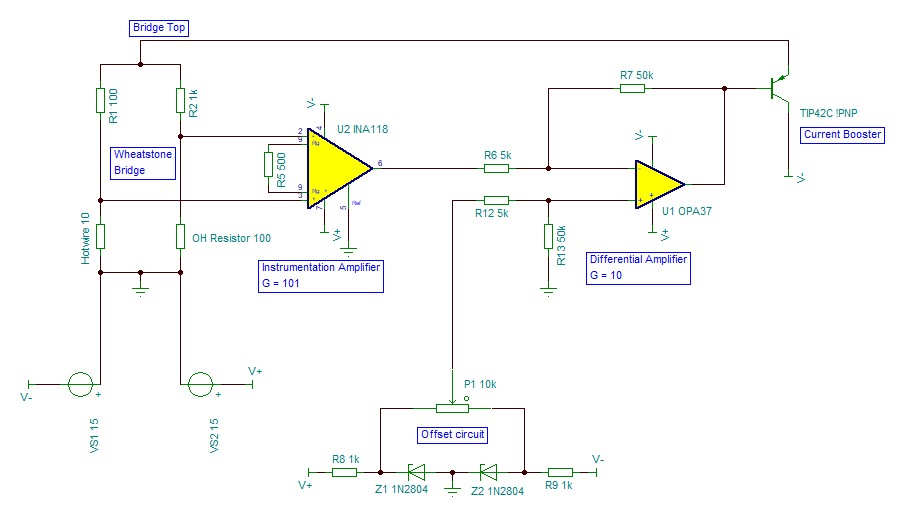
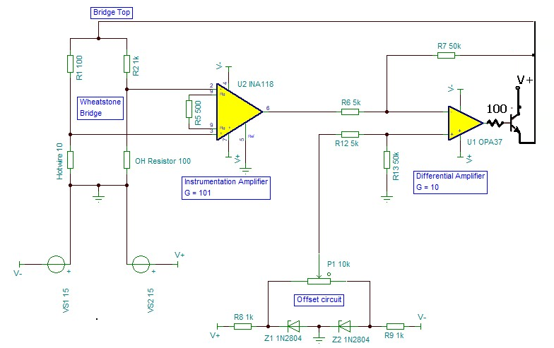
I made a Constant Temperature Anemometer using this and this as reference. However, I'm having trouble in making it work properly. To get the circuit started I need the emitter voltage (Bridge Top) to be negative but can't seem to get it. No papers nor discussions i searched seem to have this problem. My questions are (details below):
- I'm trying to find out what happened when a closed loop circuit like this has just turned on. Specifically, where should i start placing initial voltages to do analysis?
- How do I achieve negative voltage at the bridge top to make the circuit work properly?
- Should I change the 10k pot in the offset circuit?
When I tried this circuit, the bridge top has a positive value. This is a problem since the current booster is a PNP. The base voltage is 13V, which is above the emitter-base breakdown voltage. I assume the problem is because when I start the circuit, the initial voltage at bridge top is positive which is then amplified 1010 times and lead to saturation of the OPA37. I tried to circumvent this using a resistor between the emitter and collector like this circuit as well as placing a diode at the base like this circuit. However, it doesn't work and the bridge top is still positive even though the base voltage is already below 1V (I already replaced the transistor and verified the OPamps are not broken). Changing to NPN yields the same problem just different polarity.
I setup the offset circuit so that the pot can output voltage between ±5V using zener. However when I connected it like the circuit shown, it can't give the full ±5V range (it can't even go down to negative). I assumed the pot value is a problem due to loading effect, but TINA TI simulation proved otherwise. Not quite sure what's going on.
Note: I used a 1A ±15V Supply and a 1W resistor in place of hotwire to achieve the same condition as the simulation since it is quite complicated to factor in heat transfer. I did try using a Dantec Hotwire and have the same problem described above.


