1
\$\begingroup\$

I made a Constant Temperature Anemometer using this and this as reference. However, I'm having trouble in making it work properly. To get the circuit started I need the emitter voltage (Bridge Top) to be negative but can't seem to get it. No papers nor discussions i searched seem to have this problem. My questions are (details below):

  1. I'm trying to find out what happened when a closed loop circuit like this has just turned on. Specifically, where should i start placing initial voltages to do analysis?
  2. How do I achieve negative voltage at the bridge top to make the circuit work properly?
  3. Should I change the 10k pot in the offset circuit?

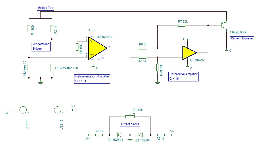
CTA Circuit

When I tried this circuit, the bridge top has a positive value. This is a problem since the current booster is a PNP. The base voltage is 13V, which is above the emitter-base breakdown voltage. I assume the problem is because when I start the circuit, the initial voltage at bridge top is positive which is then amplified 1010 times and lead to saturation of the OPA37. I tried to circumvent this using a resistor between the emitter and collector like this circuit as well as placing a diode at the base like this circuit. However, it doesn't work and the bridge top is still positive even though the base voltage is already below 1V (I already replaced the transistor and verified the OPamps are not broken). Changing to NPN yields the same problem just different polarity.

I setup the offset circuit so that the pot can output voltage between ±5V using zener. However when I connected it like the circuit shown, it can't give the full ±5V range (it can't even go down to negative). I assumed the pot value is a problem due to loading effect, but TINA TI simulation proved otherwise. Not quite sure what's going on.

Note: I used a 1A ±15V Supply and a 1W resistor in place of hotwire to achieve the same condition as the simulation since it is quite complicated to factor in heat transfer. I did try using a Dantec Hotwire and have the same problem described above.

\$\endgroup\$
7
  • \$\begingroup\$ Yes there are some simple errors but 1st define all the R values at equilibrium and output voltages. Then expected output range, gain and offset and satisfy CM input range. Generally show V+ above V- in diagrams \$\endgroup\$
    – D.A.S.
    Commented Jan 21, 2020 at 0:53
  • \$\begingroup\$ Did you try reversing the polarity between your bridge and the in-amp? \$\endgroup\$
    – brhans
    Commented Jan 21, 2020 at 1:08
  • \$\begingroup\$ Hi Tony, the bridge that I showed in the pic is in equilibrium and that would make the OPA37 output roughly be the same as the Offset circuit output. I expect the output range to be around negative 5~10V (depending on the operating condition required). I obtained the gain and offset value from references since it deals with frequency response of the system. Also I'm not sure what satisfying CM Input range means. As for the diagrams, i think flipping the opamp would make the circuit look like a mess \$\endgroup\$ Commented Jan 21, 2020 at 1:16
  • \$\begingroup\$ @brhans Yes, when the bridge top is negative, the In-amp output will be positive. Part of the OPA37 job is to reverse the In-amp output so that the transistor base is negative. Problem is, the bridge top is positive which leads to positive at the transistor base \$\endgroup\$ Commented Jan 21, 2020 at 1:23
  • \$\begingroup\$ I'm not referring to the top of the bridge. I'm referring to the inputs to U2 on pins 2 & 3 and suggesting you swap them over. \$\endgroup\$
    – brhans
    Commented Jan 21, 2020 at 1:25

1 Answer 1

1
\$\begingroup\$

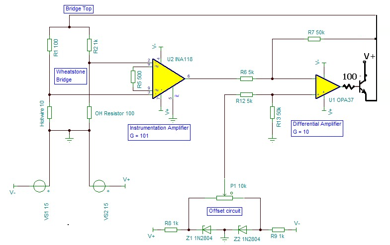
enter image description here

The bridge should be about 10% of the emitter voltage pulled up by your operating offset.

This ought to be within the Vcm input range for desired output. But you can check that.

As far as phase margin and reactive compensation , we'll leave that for another question.

\$\endgroup\$
7
  • \$\begingroup\$ Wait, so this would mean the U1 feedback resistor should be connected to the emitter? I'll also try this \$\endgroup\$ Commented Jan 21, 2020 at 1:39
  • \$\begingroup\$ Yes and you need NPN to pullup because the PNP has no pullup shown and would be inefficient as PNP emitters only pull down which the HWA already does on its own \$\endgroup\$
    – D.A.S.
    Commented Jan 21, 2020 at 2:02
  • \$\begingroup\$ The 100 Ohm resistor is optional. \$\endgroup\$
    – D.A.S.
    Commented Jan 21, 2020 at 2:08
  • \$\begingroup\$ Is it stable? ... \$\endgroup\$
    – D.A.S.
    Commented Jan 21, 2020 at 5:07
  • \$\begingroup\$ I'm still in the middle of testing. The bridge is only stable very close to the operating point. Probing the system with oscilloscope or even multimeter made it unstable. Also rotating the offset pot P1 have no effect at all to the output. I think I need to test this with a Hotwire instead of placeholder resistor. It would take some time, I'll update after testing. Sidenote: I'm still new to this site, so I'm not quite sure if I need to close this question and open another after testing. \$\endgroup\$ Commented Jan 21, 2020 at 8:26

Your Answer

By clicking “Post Your Answer”, you agree to our terms of service and acknowledge you have read our privacy policy.

Not the answer you're looking for? Browse other questions tagged or ask your own question.