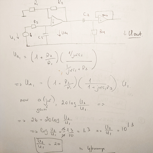
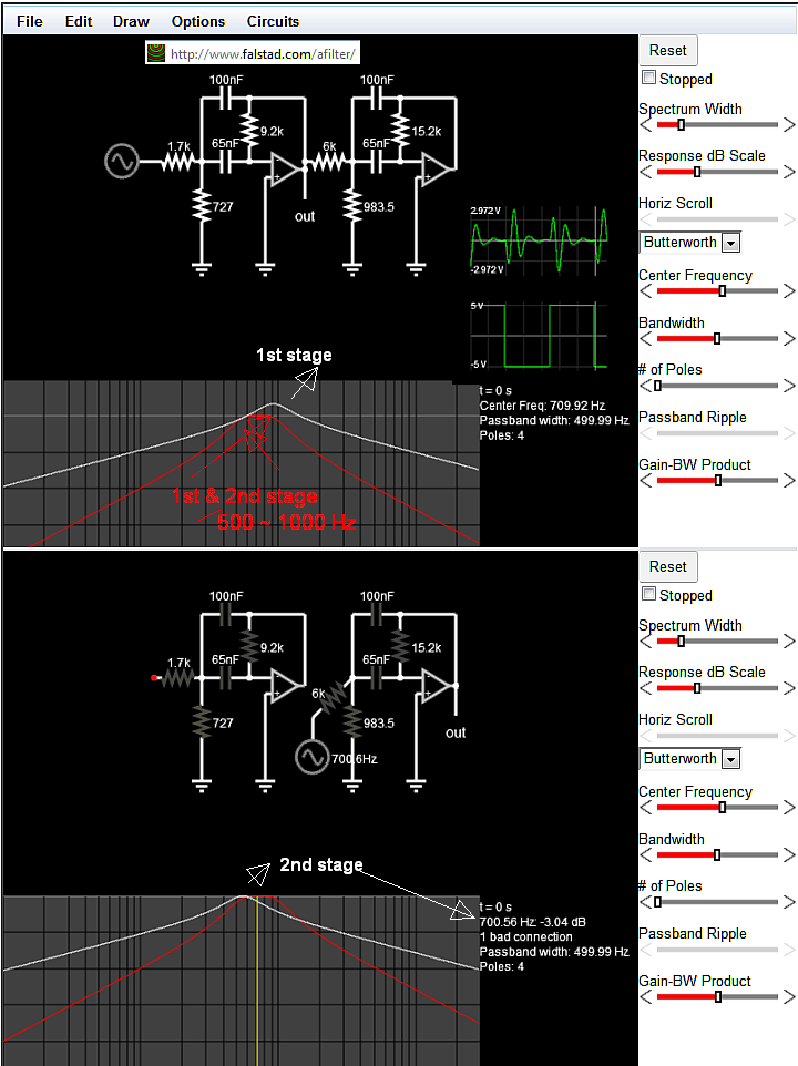
I'm making some assumptions about the filter specification:
far below the -3dB lower frequency of 500 Hz, attenuation slope is 20dB/decade
far above the -3dB upper frequency of 1000 Hz, attenuation slope is -20dB/decade
Single-pole RC stages, cascaded and buffered can almost meet this spec. Perhaps good enough.
A crude attempt at such a filter might deal with upper and lower -3dB points separately. Very easy to calculate:
But its wrong...midband gain when cascaded is less than desired. Of course, the opamp can make up this lack of gain. But the two frequencies where the output falls 3dB below midband gain are not 500 Hz, and 1000 Hz. Those two frequencies are just too close to one another. Were they much farther separated, this simple solution could be good enough.
As is, their separate responses interact, making the proper solution somewhat more complex (pun intended). One might question if the OP's circuit topology could achieve the spec...
Suppose we make both corner frequencies the same (at the geometric mean, at 707.107 Hz.). Mid-band gain not including opamp gain is -6dB: -3dB from low-pass and -3dB from high-pass.
Where do the two cascaded -3dB frequencies fall, relative to mid-band gain? Alas, below 500 Hz, and above 1000 Hz. Conclusion - the OP's circuit topology cannot meet the spec. A higher circuit Q is required.


