I am trying to simulate the results I see when using a constant temperature anemometer circuit to sense air flow. An excellent discussion can be found: arduino thermal anemometer.
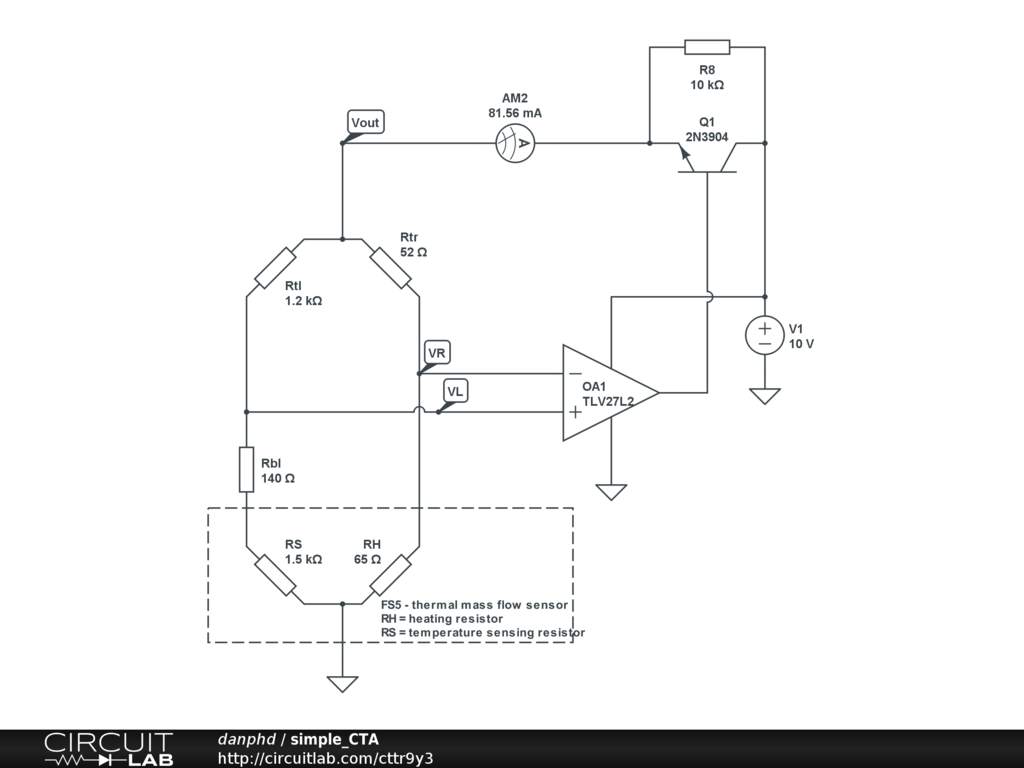
Here is my simulated circuit: https://www.circuitlab.com/circuit/ttr9y3/simple_cta/

The basic principle of the FS5 sensor (as I understand) is that there are 2 resistors, 1 to heat (RH = 45 Ohms) and 1 to temperature sense (RS = 1200 Ohms). The circuit is designed so that a constant temperature differential is maintained, i.e. when air flows through cooling the sensing resistor, it's resistance decreases, the bridge becomes unbalanced, the op amp activates the transistor, which then allows current to be drawn into the heating resistor in an attempt to re-balance the bridge. Therefore, the bridge voltage is proportional to the air flow.
I am getting the right results in practice with Vout=5V-10V depending on flow, and at rest I read:
- Vout = 5V
- AM2 = 40mA
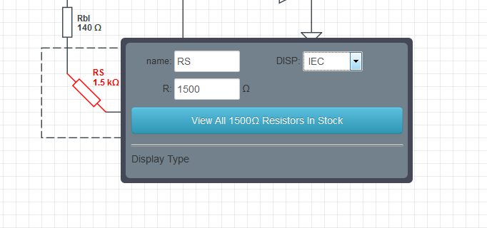
- RS = 1500 Ohms
- RH = 65 Ohms
However, when I try to simulate this, I am getting Vout=9.2V and AM2=82mA! The DC Sweep should show that as RS decreases, Vout increases, yet this is also not the case.
This has been bugging me for a while now, please help me understand why this circuit works in reality, but not in theory! What am I doing wrong??

