4
\$\begingroup\$

I'm currenly taking a course in Analog Circuits in the university and we got a task that requires us to design an amplifier, with characteristics that depend on our ID numbers. My amp should be a voltage amplifier, with the following requirements:

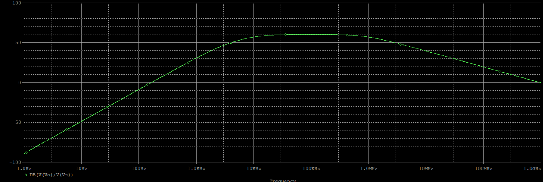
  • A = 59 dB
  • f_3db_low = 10 kHz, f_3db_high = 1 MHz (BW is approx. 1 MHz)
  • slope of rising (in Bode) = 40dB/Dec
  • slope of falling (in Bode) = -20dB/Dec

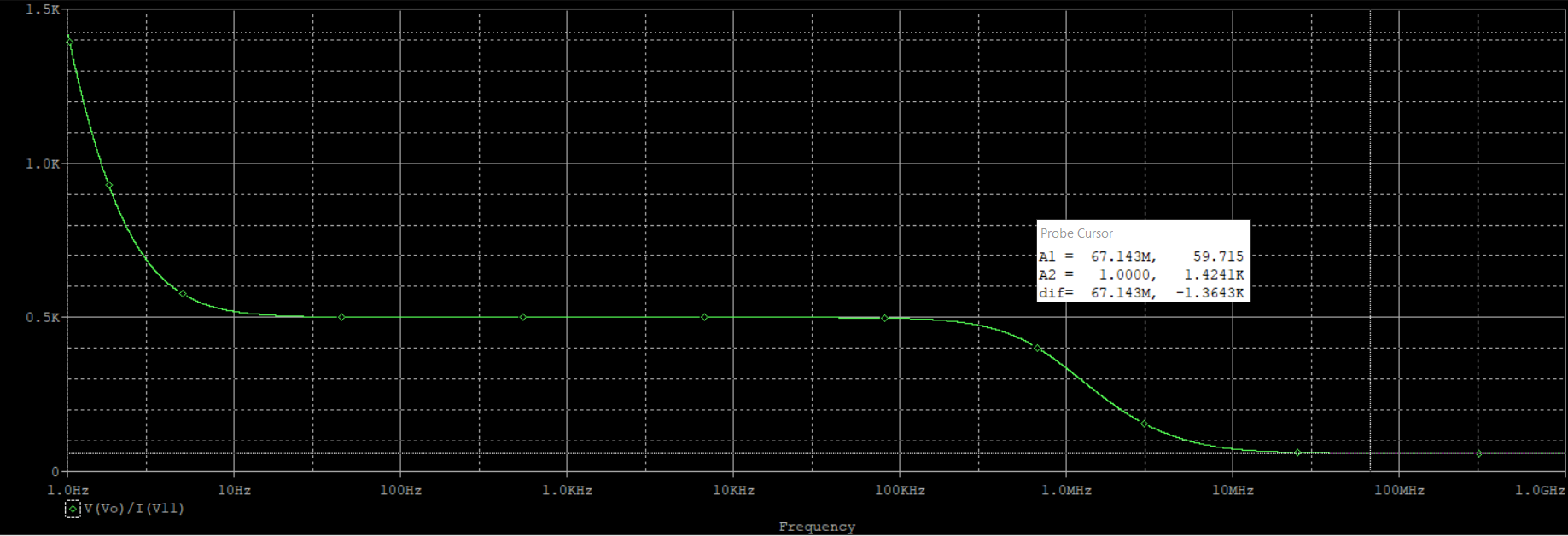
and in the frequency range 0.1 kHz < f < 100 MHz, the input & output resistances should be: R_in = 54 kOhm, R_out = 59 Ohm.

(Due to large R_in and small R_out, the amp is voltage amplifier)

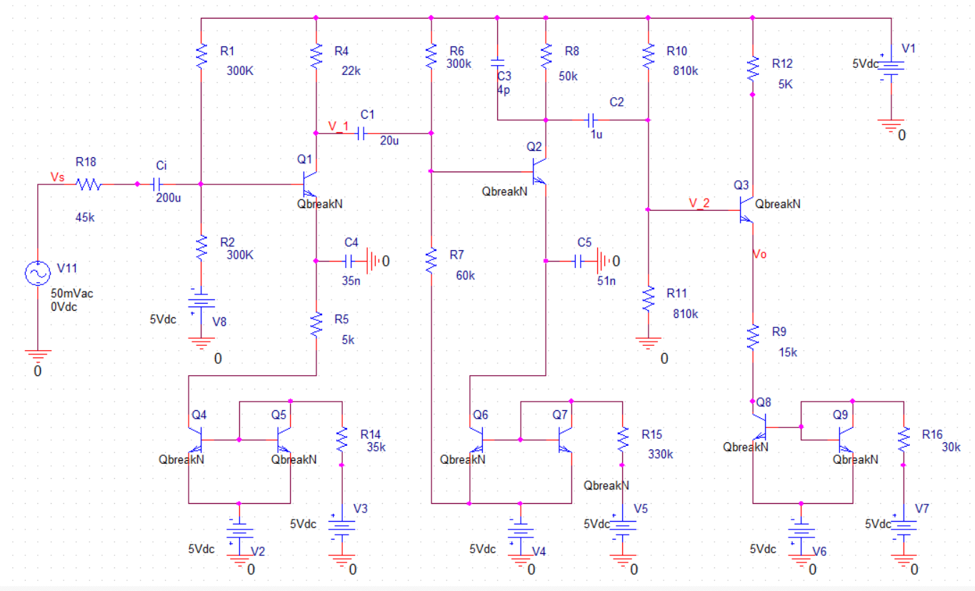
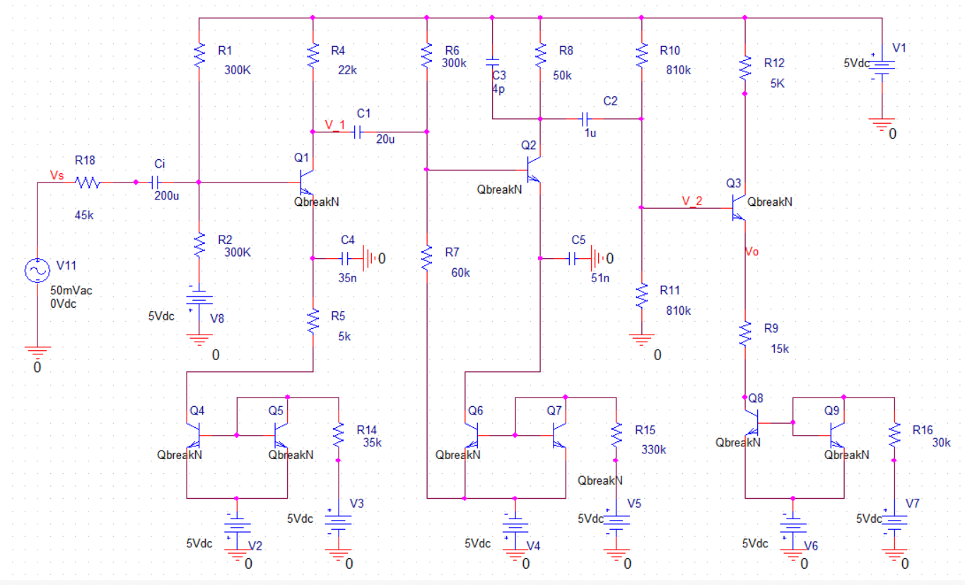
The following circuit I designed satisfies all the conditions are satisfied, except the input & output impedances. I tried a lot of things, but it seems that everything I try just destroys the amplification, which is perfect to me.

I'm attaching a schematic of the circuit, Bode plot of the gain, R_in as a function of f, and R_out as a function of f (in this order):

The circuit:
Gain plot:
R_in:

R_out:
the circuit is based on CE, CE, CC stages with current mirror to each stage.

enter image description here

\$\endgroup\$
5
  • \$\begingroup\$ hey, I went ahead and corrected a bit of spelling. In the report you write, please make sure that you use correct CapITalIzaTIon of units, please. It's kHz, and dB, not KHZ and Db. \$\endgroup\$ Commented Jan 24, 2020 at 18:09
  • \$\begingroup\$ Where did the value for \$R_{18}\$ come from, exactly? (I don't see you mentioning the source impedance being that value and I usually consider a resistor in that position as representing the source impedance and not a part of the circuit in question.) \$\endgroup\$
    – jonk
    Commented Jan 24, 2020 at 18:47
  • \$\begingroup\$ Thank you for the correction Marcus. About R18: it is indeed a part of the circuit, and if I'm not wrong, it is the Thevenin Equivalent of the circuit. In university we represent circuits with Rs conncted to the source. In this circuit, it affects the amplification (voltage divider on the input voltage [base voltage of Q1]), and also the input impedance. We started the design with analytical calculations, but since some of them were wrong, we changed some parameters arbitrarily, until we got what we wanted. For these parameters, the input voltage starts to stabilize only at 100kHz. \$\endgroup\$
    – Itai Dotan
    Commented Jan 24, 2020 at 19:25
  • \$\begingroup\$ @ItaiDotan I'm may not be following you. So let me ask this a slightly different way. Did you intentionally insert \$R_{18}\$ in order to increase the apparent source impedance to a value you wanted to achieve? (If so, what's the source impedance of your driving source? It cannot be zero.) May I also assume you can't use opamps and that you don't know anything about bootstrapping? How do you expect to achieve your output impedance with an emitter follower? It's great "pulling upward" because the emitter will just follow in that direction, but it is terrible when pushing downward on the load. \$\endgroup\$
    – jonk
    Commented Jan 24, 2020 at 21:12
  • \$\begingroup\$ As you said, I did insert R18 in order to increase the impedance that the source "sees". I'm not so sure what do you mean by "driving source". I did not use opamps because I'm allowed to use only BJT's, resistors and capacitors, and I am aware to the concept of bootstrapping, but the less complicated and less stages I will have, the better the grade will be. Also, as I mentioned, I'm an undergrad student so my knowledge is not too wide in this subject. If you have any recommendations, I would be happy to hear them. Thanks \$\endgroup\$
    – Itai Dotan
    Commented Jan 25, 2020 at 0:20

1 Answer 1

1
\$\begingroup\$

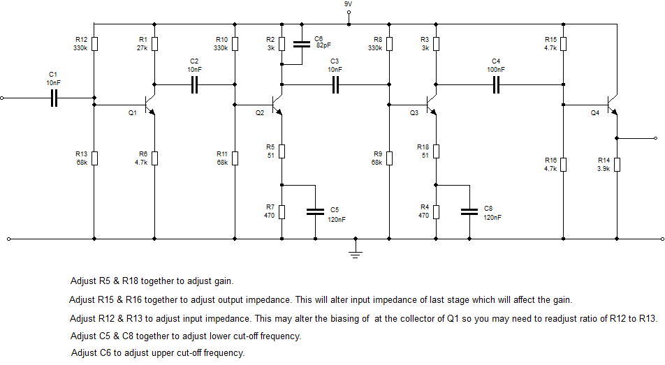
The input impedance is frequency dependent because of C4 in your circuit. Add an additional stage on the input without a capacitor in its emitter circuit.

R10 & R11 in your circuit have a bearing on the output impedance and they are too high in value. Reduce these values but this will reduce the gain as it will reduce the input impedance of the last stage. Find some replacement gain from the added extra input stage. R12 is not needed in your circuit.

The circuit below may not be perfect (say on output impedance, I don’t want to do your homework for you) but it’ll give you a good idea of what’s required as a progression. Try adjusting the values of various components and see how it affects the simulations to improve learning.

Transistor Amp

Transistor Amp

Set-up procedure would be (in order):

1) Set the I/P impedance by adjusting R5.

2) Set the O/P impedance by adjusting R9 & R10.

3) Set the Gain by adjusting R15 & R16.

4) Finally set the cut off frequencies by adjusting relevant capacitors.

This would be worth doing from a learning point of view and would give you an alternative design.

\$\endgroup\$
4
  • \$\begingroup\$ Thank you for answering James! Do you think that the current mirrors are unnecessary for my task? I thought that since I can set the current with them, it will give me more freedom in setting the resistors and thus the gain. \$\endgroup\$
    – Itai Dotan
    Commented Jan 25, 2020 at 10:28
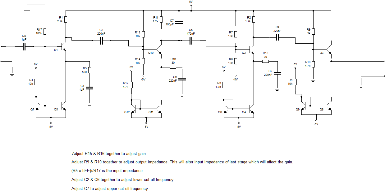
  • \$\begingroup\$ Using a current mirror as a constant current source like that in a common emitter amplifier is a very unconventional approach. I have never seen that before. I have used the classical approach in my circuit where the emitter current is set by setting the emitter voltage with the two base bias resistors. The emitter current (and hence the collector current) is then approximately the emitter voltage divided by the emitter resistance. The collector current then drops a voltage across the collector resistor setting the dc collector bias. \$\endgroup\$
    – user173271
    Commented Jan 25, 2020 at 14:45
  • \$\begingroup\$ After a lot of adjusting I made to the circuit you suggested, I have finally achieved what I wanted. Thank you very much again! \$\endgroup\$
    – Itai Dotan
    Commented Jan 25, 2020 at 17:34
  • \$\begingroup\$ Good, good. Just for completeness I've added a design with the current mirror technique included. \$\endgroup\$
    – user173271
    Commented Jan 25, 2020 at 18:06

Your Answer

By clicking “Post Your Answer”, you agree to our terms of service and acknowledge you have read our privacy policy.

Not the answer you're looking for? Browse other questions tagged or ask your own question.