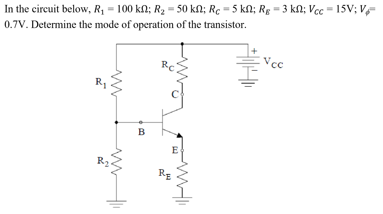
 I tried finding the Thevenin equivalent of the input loop by using voltage divider to find Vb and Rb. And using Kirchoff's Voltage law on the input loop. But I'm stuck because there is no value for Beta. I also tried using simultaneous equations to work out if I could find the values for Ib and Beta but to no avail. I did assume the model to be active mode, I got stuck. Then I assumed it to be saturation mode and i still got stuck. Please help
-
3\$\begingroup\$ 1) no need for Thevenin, why are you using it? I don't need it. 2) assume that \$\beta\$ is large, so large that the base current doesn't affect the voltage at "B", 3) Use R1, R2 and Vcc to determine the voltage at "B" (remember that we assumed \$I_B\$ = 0. 4) realize that Base-Emitter is a diode and that there will be a certain voltage across that, like 0.7V. Now we know the voltage at "E". \$\endgroup\$– BimpelrekkieCommented Apr 28, 2020 at 9:03
-
4\$\begingroup\$ 5) Calculate the current through \$R_E\$ 6) What will \$I_C \$ be? What will the voltage at "C" be? 7) Now assume \$\beta\$ = 100 and everything else stays the same. What will \$I_B\$ be? How will that affect the voltage at "B"? Next time: start by assuming \$\beta\$ = 100 and see what you get. Then try \$\beta\$ = 10 and \$\beta\$ = 1000, is there a large difference? In many circuits there isn't as a properly designed circuit will work with a \$\beta\$ of 50 or higher. That's because the \$\beta\$ of transistors vary a lot, the variation needs to be taken into account. \$\endgroup\$– BimpelrekkieCommented Apr 28, 2020 at 9:08
-
\$\begingroup\$ What is the core of Bimpelrekkie`s fine answer? The BJT is voltage-controlled (and not ciurrent-controlled as some people believe). Therefore, during design of such an amplifier, the base current (and its variations/uncertainties) plays a minor role only (and can often be neglected). This is true, in particular, when there is an emitter resistor that drastically reduces the influence of Vbe-variations (resp. uncertainties) on the collector current. \$\endgroup\$– LvWCommented Apr 28, 2020 at 12:37
-
\$\begingroup\$ Saturation just begins to occur when the collector voltage reaches the base voltage and just starts to decline below the base voltage. So this means about when \$V_\text{CE}=700\:\text{mV}\$ in your given case (since the problem makes that a constant value.) You should develop a formula that computes \$V_{\text{CE}_{\left(\beta\right)}}\$ and plot it out for \$0\le \beta\le \infty\$ and see what the plot looks like. It should open your eyes. Can you attempt to provide that equation? \$\endgroup\$– jonkCommented Apr 29, 2020 at 4:33
1 Answer
Let's assume that you knew what you were doing when you wrote:
I tried finding the Thevenin equivalent of the input loop by using voltage divider to find Vb and Rb. And using Kirchoff's Voltage law on the input loop.
I'm willing to accept your assurances because you wrote that close enough to what I might expect. So let's just write that out (I'll assume here that you know why I'm writing it out this way without having to re-draw the schematic and point out the obvious to you):
$$\begin{align*}R_\text{TH}&=\frac{R_1\cdot R_2}{R_1+R_2}&V_\text{TH}&=V_\text{CC}\cdot\frac{R_1}{R_1+R_2}\\\\I_\text{B}&=\frac{V_\text{TH}-V_\text{BE}}{R_\text{TH}+\left(\beta+1\right)\cdot R_\text{E}}&I_\text{C}&=\beta\cdot I_\text{B} & I_\text{E}&=\left(\beta+1\right)\cdot I_\text{B}\\\\V_\text{B}&=V_\text{TH}-I_\text{B}\cdot R_\text{TH}&V_\text{C}&=V_\text{CC}-I_\text{C}\cdot R_\text{C}&V_\text{E}&=I_\text{E}\cdot R_\text{E} \end{align*}$$
From this, you can easily compute:
$$\begin{align*}V_\text{CE}&=V_\text{C}-V_\text{E}=V_\text{CC}-I_\text{C}\cdot R_\text{C}-I_\text{E}\cdot R_\text{E}\\\\&=V_\text{CC}-\beta\cdot I_\text{B}\cdot R_\text{C}-\left(\beta+1\right)\cdot I_\text{B}\cdot R_\text{E}\\\\ &=V_\text{CC}-I_\text{B}\cdot \big[\beta\cdot R_\text{C}-\left(\beta+1\right)\cdot R_\text{E}\big]\\\\&=V_\text{CC}-\frac{V_\text{TH}-V_\text{BE}}{R_\text{TH}+\left(\beta+1\right)\cdot R_\text{E}}\cdot \big[\beta\cdot R_\text{C}-\left(\beta+1\right)\cdot R_\text{E}\big] \end{align*}$$
Plot that as a function of \$\beta\$ and see what you get. What is the value with \$\beta=0\$? What is the value as \$\beta\to\infty\$? I think you should now be able to see why a precise value for \$\beta\$ isn't necessary here.
